
| Type | Resistance values R [Ohm] |
Continuous output P [W] |
Max. operating voltage U [V] |
| BW D 158 / 3000 | 10 – 200 | 3000 | 1000 |
|---|---|---|---|
| BW D 158 / 5000 | 10 – 200 | 5000 | |
| BW D 158 / 6000 | 10 – 200 | 6000 | |
| BW D 158 / 10000 | 6 – 500 | 10.000 | |
| BW D 158 / 15000 | 4 – 600 | 15.000 | |
| BW D 158 / 20000 | 3 – 600 | 20.000 | |
| BW D 158 / 30000 | 2,1 – 750 | 30.000 | |
| BW D 158 / 45000 | 2,1 – 8004 | 5.000 | |
| BW D 158 / 60000 | 2 – 850 | 60.000 |
*Other resistance values available upon request.
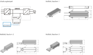
| Type | Dimensions | Connection | Design type | ||||||
|---|---|---|---|---|---|---|---|---|---|
| L1 [mm] |
L2 [mm] |
L3 [mm] |
B1 [mm] |
B2 [mm] |
H [mm] |
Cable gland | Terminal | ||
| BW D 158 / 3000 | 320 | 213 | 500 | 190 | 175 | 68 | M20 | 6 mm² | BF 1 |
| BW D 158 / 5000 | 450 | 343 | 500 | 190 | 175 | 68 | M20 | 6 mm² | BF 1 |
| BW D 158 / 6000 | 550 | 443 | 500 | 190 | 175 | 68 | M20 | 6 mm² | BF 1 |
| BW D 158 / 10000 | 680 | 343 | 265 | 176 | 156 | 170 | M25 | 10 mm² | BF 2 |
| BW D 158 / 15000 | 680 | 343 | 265 | 245 | 225 | 170 | M32 | 10 mm² | BF 3 | BW D 158 / 20000 | 680 | 343 | 265 | 2 x 176 | 2 x 156 | 170 | M32 | 10 mm² | 2 x BF 2 | BW D 158 / 30000 | 680 | 343 | 265 | 2 x 245 | 2 x 225 | 170 | M32 | 10 mm² | 2 x BF 3 | BW D 158 / 45000 | 680 | 343 | 265 | 3 x 245 | 3 x 225 | 170 | M32 | 16 mm² | 3 x BF 3 | BW D 158 / 60000 | 680 | 343 | 265 | 4 x 245 | 4 x 225 | 170 | M32 | 16 mm² | 4 x BF 3 |
- Temperature switch
The power ratings apply for continuous duty. The power ratings can be increased in short-time operation in function of duty cycle by multiplication with the relevant factor from the diagram below or according to the formula as follows.The resistance values refer to standard products with a standard tolerance of +/- 10 % with an ambient temperature of 20 °C. The resistance value insignificantly changes in function of the winding temperature. Therefore, resistance changes of approx. +10 % in comparison to the cooled-down conditions may occur.
All data and configurations can be found in our product datasheet.