
Test Choke RPD 9039

Three-phase load reactor Description Drive inverters or output filters must be tested at nominal current, a process typically performed using motor-generator sets. Due to the high costs, test specimens can alternatively be loaded with Chokes that offer sufficient linearity and do not exceed the temperature limit at higher frequencies. Advantages small dimensions Cost-effective solution Technical data Cooling: AN Insulation class F Climatic category: 25/085/21 DIN IEC 68 Part 1 Max. winding temperature: 140 °C Protection rating: IP 00 Rated voltage : 400 V Rated current : 0,6 – 75 A Inductance : 3,15 – 254 mH Type Rated voltage [V] Rated current [A] Inductance [mH] DC-Resistance [mΩ] Power loss [W] RPD 9039/0,6 3 x 400 0,6 254 6009,2 20 RPD 9039/7,0 3 x 400 7 31,4 221,7 70 RPD 9039/32,0 3 x 400 32 8,550 34,3 230 RPD 9039/75,0 3 x 400 75 3,150 12,6 430 Dimensions in MM Type L [mm] B [mm] H [mm] N1 [mm] N2 [mm] øD1 [mm] øD1 [mm] A1 [mm] Copper [kg] Weight [kg] RPD 9039/0,6 125 91 85 100 52 5 x 8 9 33,1 1 2 RPD 9039/7,0 190 123 157 170 79 8 x 12 9 34,5 3 10 RPD 9039/32,0 300 168 264 224 120 10 x 18 9 34,7 11 38 RPD 9039/75,0 360 182 313 264 142 10 x 18 9 35,7 18 58
Test reactor NPT 8929
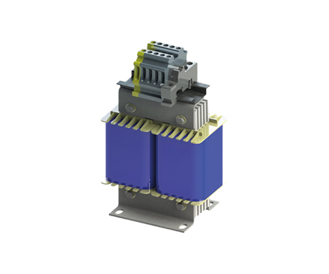
Single-phase test reactor Description These chokes are used in test laboratories as load chokes. They can be interconnected (almost) arbitrarily. If these chokes are used with appropriate resistors, testing under various cos(phi) is possible. This is required, for example, to test the connection and switching behavior of components Advantages Robust design High flexibility compact design Low losses Technical data Insulation class: F at 40° C Climatic category: 25/085/21 DIN IEC 68 Part 1 Max. winding temperature: 125° C Protection class: IP00 Nominal Voltage: 230 V Rated current: 0,5 – 32,5 A Inductance: 0,127 – 3180 mH Type Rated voltage [V] Rated current [A] Inductance [mH] DC-Resistance [mΩ] Power loss [W] NPT 8929 / 0,5 230 0,5 3180 55670,2 23 NPT 8929 / 1,25 230 1,25 1270 16880,0 43 NPT 8929 / 1,66 230 1,66 955 9977, 8 47 NPT 8929 / 2,5 230 2,5 636 6388,5 66 NPT 8929 / 5 230 5,0 318 1782,5 94 NPT 8929 / 32,5 230 32,5 0,318 0,0 39 NPT 8929 / 32,5 230 32,5 0,127 7,0 13 NPT 8929 / 32,5 230 32,5 0,318 0,0 27 Dimensions in MM Type L [mm] B [mm] H [mm] N1 [mm] N2 [mm] øD1 [mm] Connection [mm²] Copper [kg] Weight [kg] NPT 8929 / 0,5 120 96 205 76 77 7 x 13 2,5 0,7 5 NPT 8929 / 1,25 160 105 265 100 81 7 x 13 2,5 2 9,8 NPT 8929 / 1,66 160 115 270 100 91 7 x 13 2,5 3,1 12,2 NPT 8929 / 2,5 200 122 310 124 94 10 x 18 4 3,9 17 NPT 8929 / 5 240 153 355 144 125 10 x 18 4 7,3 29 NPT 8929 / 32,5 120 96 208 76 77 7 x 13 16 0,84 6,5 NPT 8929 / 32,5 100 82 190 63 65 6 x 10 16 0,44 3,6 NPT 8929 / 32,5 120 96 208 76 77 7 x 13 16 0,94 6,5
Test Reactor NPT 8919

Single-phase iron core reactor Description These chokes are used as load chokes in testing laboratories. They can be interconnected (almost) arbitrarily. If these chokes are used with appropriate resistors, testing is possible under various cos(phi). This is required, for example, to test the connection and switch-on behavior of components. Advantages Robust design High flexibility compact design Low losses Technical data Insulation class: F at 40° C Climatic category: 25/085/21 DIN IEC 68 Part 1 Max. winding temperature: 125° C Protection class: IP00 Nominal voltage: 230 – 600 V Nominal current: 1.5 – 32.5 A Inductance: 0.031 – 71 mH Optional extras Also available as IP 54 with: Input cable/output cable Input cable/output socket Complete cable connection solution for mains, output and control connections
Line reactor N CNW 905
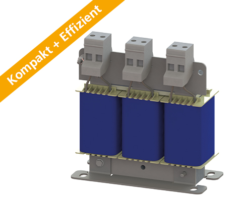
Line reactor N CNW 905 Three-phase line reactor 2% Uk DESCRIPTION NEW SERIES! The new series not only scores points for its faster delivery time, but also for its resource conservation and increased efficiency. Power Noise Reduction – save up to 15% energy costs. A line reactor relieves the supply network by compensating the harmonics reactive power. The harmonics and commutation notches are reduced strongly. By using a line reactor the inverter electronics and DC-capacitors will be protected. Starting currents and current peaks are reduced up to 30%. Line reactors help to comply with international power quality standards IEEE 519 or EN 61000-3-2. ADVANTAGES Compact design Extended service life of electrical consumers Low-temperature rise Attenuation of current spikes up to 30% Reduction of input current up to 15% Low-noise Production possible according to UL insulation system E251513 Typical applications Drive systems for motor drives: Mechanical engineering, Elevators / escalators, Pipes, Conveyor technology, Ventilation and air conditioning, Robotics, Automation technology, Power supplies and Wind turbines Technical Data Rated voltage: U ≤ 3 x 500 V Short circuit: Uk 2% (400VAC/50Hz, INenn) Frequency: 50/60 Hz According to: EN 60289 / EN 61558 Test voltage: LL 2500 V, DC 1min; L-PE 2500 V, DC 1min Insulation class: T40/F Protection rating: IP00 Climatic category: DIN IEC 60068-1 Overload: 1,5 x INenn 1 min / h Design: standing on foot angle TECHNICAL SPECIFICATION Type Nominal voltage / nominal frequency UN [V] Nominal current IN [A] Inductance L [mH] Losses P [W Weight [kg Weight Cu [kg] Weight Al [kg] N CNW 903 /3 500 50 / 60 Hz 3 9,800 16 1.0 0.2 – N CNW 903 /6 500 50 / 60 Hz 6 4,880 25 2.0 0.3 – N CNW 903 /8 500 50 / 60 Hz 8 3,680 35 2.0 0.3 – N CNW 903 /10 500 50 / 60 Hz 10 2,930 36 3.0 0.4 – N CNW 903 /12 500 50 / 60 Hz 12 2,450 38 3.0 0.45 – N CNW 903 /16 500 50 / 60 Hz 16 1,830 48 4.0 0.7 – N CNW 903 /25 500 50 / 60 Hz 25 1,170 63 5.2 0.8 – N CNW 903 /36 500 50 / 60 Hz 36 0,810 67 7.0 1.9 – N CNW 903 /50 500 50 / 60 Hz 50 0,590 112 9.0 1.2 – N CNW 903 /70 500 50 / 60 Hz 70 0,420 180 11 2.1 – N CNW 903 /90 500 50 / 60 Hz 90 0,330 144 17 2.5 – N CNW 903 /110 500 50 / 60 Hz 110 0,270 179 18 1.8 – N CNW 903 /125 500 50 / 60 Hz 125 0,235 220 17 2.6 – N CNW 903 /160 500 50 / 60 Hz 160 0,180 145 22 5.0 – N CNW 903 /200 500 50 / 60 Hz 200 0,147 187 26 1.3 3.8 N CNW 903 /250 500 50 / 60 Hz 250 0,118 254 35 1.3 3.0 N CNW 903 /300 500 50 / 60 Hz 300 0,098 250 37 1.3 4.7 N CNW 903 /350 500 50 / 60 Hz 350 0,084 267 45 2.6 5.0 N CNW 903 /400 500 50 / 60 Hz 400 0,074 365 52 2.6 5.2 N CNW 903 /500 500 50 / 60 Hz 500 0,059 423 58 2.9 7.8 N CNW 903 /600 500 50 / 60 Hz 600 0,049 450 71 5.0 6.9 N CNW 903 /700 500 50 / 60 Hz 700 0,042 493 88 5.0 9.2 N CNW 903 /800 500 50 / 60 Hz 800 0,037 545 96 5.1 8.3 N CNW 903 /900 500 50 / 60 Hz 900 0,033 655 108 12.5 10.1 N CNW 903 /1000 500 50 / 60 Hz 1000 0,029 775 108 12.5 10.1 N CNW 903 /1200 500 50 / 60 Hz 1200 0,024 1009 133 13.9 12.4 DIMENSIONS IN MM Type Lenght L1 (mm) Lenght L2 (mm) Broad B1 (mm) Broad B2 (mm) High max. H1 (mm) Mounting N1 (mm) Attachment N2 (mm) Attachment D1 (mm x mm) Clamp/ Cable Lug [mm²] Angle [mm x mm] Connection A1 (mm) Connetion D2 (mm) PE N CNW 903 /3 65 78 50 60 95 50 38 5 x 8 2.5 M4 N CNW 903 /6 80 96 55 65 110 56 43 5 x 8 2.5 M4 N CNW 903 /8 125 120 61 66 130 100 45 5 x 8 2.5 M4 N CNW 903 /10 125 120 71 76 130 100 55 5 x 8 2.5 M4 N CNW 905 /12 125 120 71 76 130 100 55 5 x 8 2.5 M4 N CNW 903 /16 155 150 76 76 155 130 54 8 x 12 2.5 M4 N CNW 903 /25 155 150 91 101 170 130 69 8 x 12 10 M4 N CNW 903/36 190 180 81 91 195 170 57 8 x 12 10 M6 N CNW 903 /50 190 180 101 111 195 170 77 8 x 12 10 M6 N CNW 903 /70 230 136 200 176 73 9 x 13 16 (M8) 45 M8 N CNW 903 /90 230 150 200 176 95 9 x 13 16 (M8) 45 M8 N CNW 905 /110 240 150 210 185 97 10 x 18 16 (M8) 45 M8 N CNW 905 /125 240 150 210 185 95 10 x 18 45 M8 N CNW 903 /160 240 175 210 185 103 10 x 18 35 (M10) 55 M8 N CNW 903 /200 300 148 270 224 95 10 x 18 30 x 4 39 11 M12 N CNW 903 /250 300 184 270 224 125 10 x 18 30 x 4 39 11 M12 N CNW 903 /300 300 190 270 224 125 10 x 18 30 x 4 39 11 M12 N CNW 903 /350 340 192 305 248 130 10 x 18 40 x 5 49 13 M12 N CNW 903 /400 360 195 315 264 142 10 x 18 40 x 5 49
Mains choke N CNW 903

Three-phase mains choke 4% Uk DESCRIPTION NEW SERIES! The new series not only scores points for its faster delivery time, but also for its resource conservation and increased efficiency. Power Noise Reduction – save up to 20% energy costs. A line reactor relieves the supply network by compensating the harmonics reactive power. The harmonics and commutation notches are reduced much. By using a line reactor the inverter electronics and DC-capacitors will be protected. Starting currents and current peaks are reduced up to 60%. Line reactors help to comply with international power quality standards IEEE 519 or EN 61000-3-2. ADVANTAGES Compact design Extended lifetime of electrical consumers Low-temperature rise Attenuation of current spikes up to 60% Reduction of input current up to 20% Low-noise Production according to UL insulation system E251513 is possible TYPICAL APPLICATIONS Drive systems for motor drives: Mechanical engineeringPumpen,Conveyortechnology,Ventilation and air conditioning,Robotics,Automation technology,Power supplies TECHNICAL SPECIFICATION Rated voltage: U ≤ 3 x 500 V Short circuit: Uk 4% (400VAC/50Hz, INenn) Frequency: 50/60 Hz According to: EN 60289 / EN 61558 Test voltage: L-L 2500 V, DC 1min; L-PE 2500 V, DC 1min Insulation class: T40/F Protection rating: IP 00 Climatic categorie: DIN IEC 60068-1 Overload: 1,5 x INenn 1 min / h Design: mounted on foot print TECHNICAL SPECIFICATIONS Type Nominal voltage UN [V] Nominal current IN [A] Inductance L [mH] Losses P [W] Weight[kg] [kg] Weight Cu [kg Weight Al [kg] N CNW 903 /3 500 50 / 60 Hz 3 9,800 16 1,0 0,2 N CNW 903 /6 500 50 / 60 Hz 6 4,880 25 2,0 0,3 N CNW 903 /8 500 50 / 60 Hz 8 3,680 35 2,0 0,3 N CNW 903 /10 500 50 / 60 Hz 10 2,930 36 3,0 0,4 N CNW 903 /12 500 50 / 60 Hz 12 2,450 38 3,0 0,5 N CNW 903 /16 500 50 / 60 Hz 16 1,830 48 4,0 0,7 N CNW 903 /25 500 50 / 60 Hz 25 1,170 63 5,2 0,8 N CNW 903 /36 500 50 / 60 Hz 36 0,810 67 7,o 1,9 N CNW 903 /50 500 50 / 60 Hz 50 0,590 112 9 1,2 N CNW 903 /70 500 50 / 60 Hz 70 0,420 180 11 2,1 N CNW 903 /90 500 50 / 60 Hz 90 0,330 144 17 2,5 N CNW 903 /110 500 50 / 60 Hz 110 0,270 179 18 2,8 N CNW 903 /125 500 50 / 60 Hz 125 0,235 220 17 2,6 N CNW 903 /160 500 50 / 60 Hz 160 0,180 145 22 5,0 N CNW 903 /200 500 50 / 60 Hz 200 0,147 187 26 1,3 3,8 N CNW 903 /250 500 50 / 60 Hz 250 0,118 254 35 1,3 3,0 N CNW 903 /300 500 50 / 60 Hz 300 0,098 250 37 1,3 4,7 N CNW 903 /350 500 50 / 60 Hz 350 0,084 267 45 2,6 5,0 N CNW 903 /400 500 50 / 60 Hz 400 0,074 365 52 2,6 5,2 N CNW 903 /500 500 50 / 60 Hz 500 0,059 423 58 2,9 7,8 N CNW 903 /600 500 50 / 60 Hz 600 0,049 450 71 5,0 6,9 N CNW 903 /700 500 50 / 60 Hz 700 0,042 493 88 5,0 9,2 N CNW 903 /800 500 50 / 60 Hz 800 0,037 545 96 5,1 8,3 N CNW 903 /900 500 50 / 60 Hz 900 0,033 655 108 12,5 10,1 N CNW 903 /1000 500 50 / 60 Hz 1000 0,029 775 108 12,5 10,1 N CNW 903 /1200 500 50 / 60 Hz 1200 0,024 1009 133 13,9 12,4 DIMENSIONS IN MM Type Lenght L1 (mm) Lenght L2 (mm) Width B1 (mm) Width B2 (mm) Height H1 (mm) Mounting N1 (mm) Mounting N2 (mm) Mounting D1 (mm x mm) Clamps/Cross section [mm²] (mm x mm) Connection A1 (mm) Connetion D2 (mm) Connection PE N CNW 903 /3 65 78 50 60 95 50 38 5 x 8 2,5 M4 N CNW 903 /6 80 96 55 65 110 56 43 5 x 8 2,5 M4 N CNW 903 /8 125 120 61 66 130 100 45 5 x 8 2,5 M4 N CNW 903 /10 125 120 71 76 130 100 55 5 x 8 2,5 M4 N CNW 903 /12 125 120 71 76 130 100 55 5 x 8 2,5 M4 N CNW 903 /16 155 150 76 76 155 130 54 8 x 12 2,5 M4 N CNW 903 /25 155 150 91 101 170 130 69 8 x 12 10 M4 N CNW 903 /36 190 180 81 91 195 170 57 8 x 12 10 M6 N CNW 903 /50 190 130 160 170 77 8 x 12 16 (M6) 45 M6 N CNW 903 /70 230 136 200 176 73 9 x 13 16 (M8) 45 M8 N CNW 903 /90 230 150 200 176 95 9 x 13 16 (M8) 45 M8 N CNW 903 /110 240 150 210 185 97 10 x 18 16 (M8) 45 M8 N CNW 903 /125 240 150 210 185 95 10 x 18 16 (M8) 45 M8 N CNW 903 /160 240 175 210 185 103 10 x 18 35 (M10) 55 M8 N CNW 903 /200 300 148 270 224 95 10 x 18 30 x 4 39 11 M12 N CNW 903 /250 300 184 270 224 125 10 x 18 30 x 4 39 11 M12 N CNW 903 /300 300 190 270 224 125 10 x 18 30 x 4 39 11 M12 N CNW 903 /350 340 192 305 248 130 10 x 18 40 x 5 49 13 M12 N CNW 903 /400 360 195 315 264 142 10 x 18 40 x 5 49 13 M12 N CNW 903 /500 360 200 345 264 142 10 x 18 40 x 5 49 13 M12 N CNW 903 /600 360 232 345 264 167 10 x 18