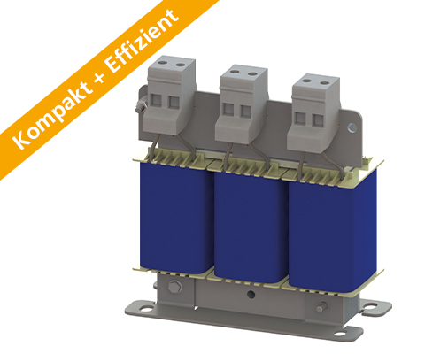
Three-phase motor choke
DESCRIPTION
NEW SERIES!
The new series not only scores points for its faster delivery time, but also for its resource conservation and increased efficiency.
Reduce voltage rise (< 200V / µs) and distortions – optimally protect electrical consumers.
In addition to voltage rises, there is a considerable amount of symmetrical and asymmetrical current distortions generated at the motor supply line due to the rapid switching of power semiconductors. These become more pronounced with increasing cable length. These disturbances can affect the motor’s performance through loud noises and, in extreme cases, through overheating. A motor choke can provide a remedy here. The motor choke reduces the voltage rise and voltage peaks between the conductors. Furthermore, the current is smoothed.
Losses and heating are minimized and leakage current is reduced. Longer motor cable lengths can be used. The motor insulation is protected, thus increasing its lifespan. The motor choke also dampens conducted interference in the lower frequency range very well. Losses and typical noises in the motor laminations are reduced. Voltage rises are reduced to (< 200V / µs.)
Increasing the service life of motors, lowering the edge steepness du / dt to earth and between the phases, reducing motor noise, and current smoothing.
ADVANTAGES
- Protection for electrical consumers
- Limitation of voltage rise to < 200V/µs
- Extended service life of electrical consumers
- Reduction of engine noise
- Low leakage currents on the motor
- Longer motor cables are possible
- Easy construction
- Compact design
- Production possible according to UL insulation system E251513
TYPICAL APPLICATIONS
Drive systems for motor drives, Mechanical engineering, Elevators / escalators, Pipes, Conveyor technology, Ventilation and air conditioning, Robotics, Automation technology, Power supplies, Wind turbines
Technical Data
- Reduction of voltage rise du/dt to < 200V/µs
- Field frequency: 0 – 60 Hz Drive
- Switching frequency of the inverter: up to 150 A >4kHz, from 150 A >1.5kHz
- According to: EN 60289 / EN 61558
- Test voltage: L-L 2500 V, AC/50Hz 60s; L-PE 2500 V, AC/50Hz 60s
- Insulation class: T40/F
- Protection rating: IP00
- Climatic category: DIN IEC 60068-1
- Overload: 1,5 x INenn 1 min / h
- Ambient temperature: 40 °C
- Design: standing on foot angle
| Type | Nominal voltage U [V] | Nominal current I [A] | Inductance L [mH] | Losses P [W] | Mass [kg] | Weight Cu [kg] | Weight Al [kg] |
|---|---|---|---|---|---|---|---|
| N CNW 854 / 2 | 500 50 / 60 Hz |
2 | 7,00 | 21 | 1,0 | 0,3 | – |
| N CNW 854 / 4 | 4 | 3,60 | 26 | 1,1 | 0,5 | – | |
| N CNW 854 / 8 | 8 | 2,00 | 35 | 2,0 | 0,5 | – | |
| N CNW 854 / 10 | 10 | 1,70 | 44 | 2,2 | 0,9 | – | |
| N CNW 854 / 12 | 12 | 1,20 | 52 | 2,7 | 0,8 | – | |
| N CNW 854 / 16 | 16 | 0,90 | 54 | 2,8 | 0,9 | – | |
| N CNW 854 / 24 | 24 | 0,70 | 55 | 4,4 | 1,9 | – | |
| N CNW 854 / 30 | 30 | 0,50 | 40 | 4,5 | 0,9 | – | |
| N CNW 854 / 37 | 37 | 0,42 | 40 | 6,0 | 1,4 | – | |
| N CNW 854 / 48 | 48 | 0,32 | 60 | 7,0 | 1,9 | – | |
| N CNW 854 / 60 | 60 | 0,28 | 80 | 7,0 | 2,0 | – | |
| N CNW 854 / 75 | 75 | 0,22 | 100 | 8,0 | 1,4 | – | |
| N CNW 854 / 90 | 90 | 0,17 | 80 | 10,0 | 1,9 | – | |
| N CNW 854 / 115 | 115 | 0,14 | 150 | 14,0 | 1,6 | – | |
| N CNW 854 / 150 | 150 | 0,11 | 170 | 16,0 | 3,1 | – | |
| N CNW 854 / 180 | 180 | 0,09 | 160 | 18,0 | 3,2 | – | |
| N CNW 854 / 200 | 200 | 0,08 | 170 | 23,0 | 2,8 | – | |
| N CNW 854 / 250 | 250 | 0,065 | 240 | 24,0 | 3,8 | – | |
| N CNW 854 / 300 | 300 | 0,053 | 380 | 44,0 | 1,5 | 2,7 | |
| N CNW 854 / 350 | 350 | 0,046 | 330 | 55,0 | 2,6 | 4,6 | |
| N CNW 854 / 400 | 400 | 0,041 | 380 | 58,0 | 2,6 | 4,9 | |
| N CNW 854 / 500 | 500 | 0,032 | 520 | 63,0 | 2,6 | 5,2 | |
| N CNW 854 / 600 | 600 | 0,028 | 650 | 65,0 | 5,0 | 5,9 | |
| N CNW 854 / 700 | 700 | 0,024 | 820 | 86,0 | 5,0 | 5,7 | |
| N CNW 854 / 800 | 800 | 0,021 | 710 | 108,0 | 6,6 | 9,0 | |
| N CNW 854 / 900 | 900 | 0,018 | 800 | 114,0 | 13,8 | 7,6 | |
| N CNW 854 / 1000 | 1000 | 0,016 | 900 | 114,0 | 13,8 | 7,6 | |
| N CNW 854 / 1200 | 1200 | 0,013 | 1170 | 122,0 | 13,8 | 8,0 |
| Type | Length L1 [mm] | Length L2 [mm] | Width B1 [mm] | Width B2 [mm] | High max. H1 [mm] | Mounting N1 [mm] | Mounting N2 [mm] | Mounting D1 [mm x mm] | Clamps / Cross section [mm²] |
Angle [mm x mm] | Connection A1 [mm] | Connection D2 [mm] | PE Ø [mm] |
|---|---|---|---|---|---|---|---|---|---|---|---|---|---|
| N CNW 854 / 2 | 80 | 96 | 45 | 55 | 110 | 56 | 34 | 5 x 8 | 2.5 | – | – | – | M4 |
| N CNW 854 / 4 | 80 | 96 | 45 | 55 | 110 | 56 | 34 | 5 x 8 | 2.5 | – | – | – | M4 |
| N CNW 854 / 8 | 80 | 96 | 55 | 65 | 110 | 56 | 43 | 5 x 8 | 2.5 | – | – | – | M4 |
| N CNW 854 / 10 | 125 | 120 | 61 | 66 | 130 | 100 | 45 | 5 x 8 | 2.5 | – | – | – | M4 |
| N CNW 854 / 12 | 125 | 120 | 71 | 67 | 130 | 100 | 55 | 5 x 8 | 2.5 | – | – | – | M4 |
| N CNW 854 / 16 | 125 | 120 | 71 | 67 | 130 | 100 | 55 | 5 x 8 | 2.5 | – | – | – | M4 |
| N CNW 854 / 24 | 155 | 150 | 76 | 86 | 170 | 130 | 54 | 8 x 12 | 10 | – | – | – | M4 |
| N CNW 854 / 30 | 155 | – | 110 | 130 | 130 | 54 | 8 x 12 | 16 (M6) | – | 40 | – | M6 | |
| N CNW 854 / 37 | 155 | – | 125 | 130 | 130 | 69 | 8 x 12 | 16 (M6) | – | 40 | – | M6 | |
| N CNW 854 / 48 | 190 | – | 115 | 165 | 170 | 57 | 57 | 8 x 12 | 16 (M8) | – | 40 | – | M8 |
| N CNW 854 / 60 | 190 | – | 115 | 165 | 170 | 57 | 57 | 8 x 12 | 16 (M8) | – | 40 | – | M8 |
| N CNW 854 / 75 | 190 | – | 135 | 160 | 170 | 67 | 67 | 8 x 12 | 16 (M8) | – | 40 | – | M8 |
| N CNW 854 / 90 | 190 | – | 135 | 160 | 170 | 77 | 77 | 8 x 12 | 16 (M8) | – | 40 | – | M8 |
| N CNW 854 / 115 | 240 | – | 145 | 145 | 210 | 185 | 84 | 84 | 10 x 18 | – | 55 | – | M10 |
| N CNW 854 / 150 | 240 | – | 145 | 145 | 210 | 185 | 94 | 94 | 10 x 18 | – | 55 | – | M10 |
| N CNW 854 / 180 | 240 | – | 155 | 155 | 210 | 185 | 94 | 94 | 10 x 18 | – | 55 | – | M10 |
| N CNW 854 / 200 | 300 | – | 160 | 270 | 224 | 95 | 95 | 10 x 18 | 25 (M12) | – | 55 | – | M12 |
| N CNW 854 / 250 | 300 | – | 160 | 270 | 224 | 95 | 95 | 10 x 18 | 25 (M12) | – | 55 | – | M12 |
| N CNW 854 / 300 | 360 | – | 180 | 315 | 264 | 137 | 137 | 10 x 18 | – | 30 x 4 | 40 | 11 | M12 |
| N CNW 854 / 350 | 360 | – | 200 | 315 | 264 | 142 | 142 | 10 x 18 | – | 40 x 5 | 50 | 13 | M12 |
| N CNW 854 / 400 | 360 | – | 215 | 315 | 264 | 157 | 157 | 10 x 18 | – | 40 x 5 | 50 | 13 | M12 |
| N CNW 854 / 500 | 360 | – | 225 | 315 | 264 | 167 | 167 | 10 x 18 | – | 40 x 5 | 50 | 13 | M12 |
| N CNW 854 / 600 | 420 | – | 215 | 365 | 316 | 144 | 144 | 13 x 20 | – | 40 x 8 | 60 | 13 | M12 |
| N CNW 854 / 700 | 420 | – | 245 | 480 | 316 | 174 | 174 | 13 x 20 | – | 40 x 8 | 60 | 13 | M12 |
| N CNW 854 / 800 | 420 | – | 255 | 480 | 316 | 174 | 174 | 13 x 20 | – | 60 x 5 | 70 | 2 x 13 | M12 |
| N CNW 854 / 900 | 420 | – | 265 | 480 | 316 | 174 | 174 | 13 x 20 | – | 60 x 10 | 80 | 2 x 13 | M12 |
| N CNW 854 / 1000 | 420 | – | 265 | 480 | 316 | 174 | 174 | 13 x 20 | – | 60 x 10 | 80 | 2 x 13 | M12 |
| N CNW 854 / 1200 | 420 | – | 275 | 480 | 316 | 184 | 184 | 13 x 20 | – | 60 x 10 | 80 | 2 x 13 | M12 |
Download our extensive catalog and discover many other REO products.


