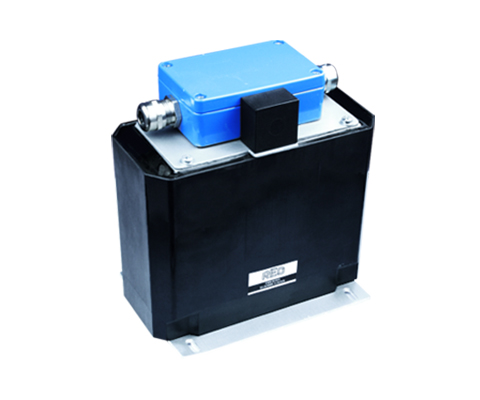
Fully encapsulated three-phase motor choke
Description
Reduce voltage rise (< 200V / µs) and distortions – optimally protect electrical consumers. Motor chokes in moulded design are specially developed for harsh environmental conditions and offer very good mechanical protection of the component. Thanks to the moulding technology, protection ratings of up to IP 66 can be achieved. The motor choke reduces the voltage rise and voltage peaks between the conductors. The current is also smoothed. Losses and heating are minimised and the leakage current is reduced. Longer motor cable lengths can be used. The motor insulation is protected and thus the service life is increased. The motor choke also dampens conducted interference in the lower frequency range very well. Losses and the typical noise in the motor plate are reduced. Voltage increases are reduced to ( < 200V / µs ). Increases the service life of motors, reduces the edge steepness du/dt to earth and between the phases, reduces motor noise, current smoothing.
Advantages
- Use in robust environment
- IP 66
- Attachment of various options: strands, terminals, strain relief, terminal box
- customer-specific mounting plate for attachment possible
- lower surface temperature
- Protection for electrical consumers
- Limitation of the voltage rise to < 500 V/µs
- extended service life for electrical consumers
- Reduction of motor noises
- low leakage currents on the motor
- longer motor cables possible
- simple assembly and compact design
- Production according to UL insulation system E251513 possible
Typical Applications
Drive technology for motor drives, e.g. mechanical engineering, elevators, escalators, pumps, conveyor technology, ventilation and air conditioning, robotics, automation technology, power supplies, wind turbines
| Type | Nominal voltage [V] |
Nominal current [A] |
Inductance [mH] |
Copper [kg] |
Total [kg] |
Strand [mm²] |
| CNW M 854 / 6 | up to 3 x 500 | 6 | 2,3 | 0,5 | 1,7 | 1,5 |
|---|---|---|---|---|---|---|
| CNW M 854 / 8 | 8 | 2,0 | 0,5 | 1,7 | 1,5 | |
| CNW M 854 / 10 | 10 | 1,7 | 0,9 | 2,8 | 1,5 | |
| CNW M 854 / 12 | 12 | 1,1 | 1,1 | 3,7 | 1,5 | |
| CNW M 854 / 16 | 16 | 0,9 | 1,1 | 3,7 | 2,5 | |
| CNW M 854 / 24 | 24 | 0,8 | 1,7 | 4,6 | 4,0 |
| Type | L1 [mm] |
B1 [mm] |
H1 [mm] |
Screw connection | Terminal | L2 [mm] |
L3 [mm] |
B2 [mm] |
H2 [mm] |
N1 [mm] |
N2 [mm] |
Ø D [mm] |
| CNW M 854 / 6 | 185 | 80 | 57 | M20 | 4 mm² | 115 | 100 | 74 | 88 | 80 | 60 | 5,5 x 7,0 |
| CNW M 854 / 8 | 185 | 80 | 57 | M20 | 4 mm² | 115 | 100 | 74 | 88 | 80 | 60 | 5,5 x 7,0 |
| CNW M 854 / 10 | 185 | 80 | 57 | M20 | 4 mm² | 140 | 125 | 77 | 113 | 100 | 60 | 5,5 x 7,0 |
| CNW M 854 / 12 | 185 | 80 | 57 | M20 | 4 mm² | 140 | 125 | 87 | 113 | 100 | 70 | 5,5 x 7,0 |
| CNW M 854 / 16 | 185 | 80 | 57 | M20 | 6 mm² | 140 | 125 | 87 | 113 | 100 | 70 | 5,5 x 7,0 |
| CNW M 854 / 24 | 190 | 80 | 57 | M25 | 6 mm² | 175 | 155 | 99 | 137 | 130 | 79 | 5,5 x 7,0 |
All data and configurations can be found in our product datasheet.

