
-
- According to: EN/IEC 61869-1/2
- Rated primary current: 1 – 50 A
- Frequency range: 50 – 400 Hz
- Rated primary current: 1 – 50 A
| Type | 1 | 3 | 5 | 10 | 25 | 50 | |
|---|---|---|---|---|---|---|---|
| 2 windings | through-hole transformer | ||||||
| Primary current [A] | IPN | 1 | 3 | 5 | 10 | 25 | 50 |
| Max. Primary current [A] | ImaxPN | 1,2 | 3,6 | 6 | 12 | 30 | 60 |
| Secondary current [mA] | IaN | 20 | 20 | 20 | 20 | 200 | 200 |
| Power [VA] | Psek | 0,1 | 0,1 | 0,1 | 0,1 | 0,12 | 0,5 |
| Transformation ratio | KN | 50 | 150 | 250 | 500 | 1000 | 1000 |
| Burden resistance [Ω] | RB | 250 | 250 | 250 | 250 | 200 | 200 |
| Burden voltage [V] | URB | 5 | 5 | 5 | 5 | 5 | 10 |
| Measuring accuracy 50 Hz [%] | FU | ≤ 1 | ≤ 1 | ≤ 1 | ≤ 1 | ≤ 1 | ≤ 1 |
| Ambient temperature [°C] | TA | -25 to + 70 | -25 to + 70 | -25 to + 70 | -25 to + 70 | -25 to + 70 | -25 to + 70 |
| Frequency range [Hz] | f | 50 – 400 | 50 – 400 | 50 – 400 | 50 – 400 | 50 – 400 | 50 – 400 |
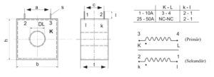
| Insulation test voltage [kVac] | VP | 3 | 3 | 3 | 3 | 3 | 3 | Connection [mm²] | 3-4/2-1 | 3-4/2-1 | 3-4/2-1 | 3-4/2-1 | NC/2-1 | NC/2-1 | Weight [kg] | 0,05 | 0,05 | 0,05 | 0,05 | 0,05 | 0,07 | Standards | EN/IEC 61869-1/2 |
| Type | PIN connection [A] |
h [mm] |
b [mm] |
t [mm] |
DL [mm] |
s [mm] |
l [mm] |
a [mm] |
c [mm] |
| IE/1 | 3-4/2-1 | 34 | 33 | 18 | 9 | 1,0 | 3,5 | 27,5 | 10 |
| IE/3 | 3-4/2-1 | 34 | 33 | 18 | 9 | 1,0 | 3,5 | 27,5 | 10 |
| IE/5 | 3-4/2-1 | 34 | 33 | 18 | 9 | 1,0 | 3,5 | 27,5 | 10 |
| IE/10 | 3-4/2-1 | 34 | 33 | 18 | 9 | 1,0 | 3,5 | 27,5 | 10 |
| IE/25 | NC/2-1 | 34 | 33 | 18 | 9 | 1,0 | 3,5 | 27,5 | 10 |
| IE/50 | NC/2-1 | 38 | 38 | 20 | 13 | 1,0 | 6,5 | 30 | 10 |