
PASSIVE CURRENT TRANSFORMER SERIES IN-I
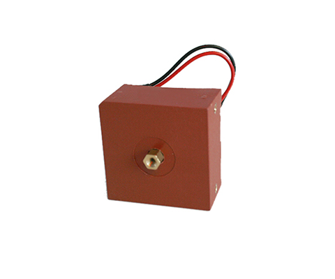
Pulse Current Transformers Description Due to the selected materials, REO pulse current transformers of the IN-I series can represent current with high accuracy and the corresponding transformation ratio – making them particularly suitable for power measurement, current monitoring and analysis, and for use in solar inverters. They are also ideally suited for use in active filters, as they can be designed for measuring current peaks. The primary current is measured via a current conductor that passes through the closed toroidal core. The magnetic field generated by the current flow through the conductor is absorbed by the toroidal core and, according to the transformation ratio of the secondary winding, generates a smaller current for measurement purposes. This method reduces a high measurement current to a significantly smaller current and additionally separates it from the primary circuit by means of safe galvanic isolation. Advantages Very precise current measurement Class 0.2 Pulse current measurement Low-loss core (core losses <10W/kg at 20kHz/200mT) Housing made of UL VO material (Conductor must be positioned) Diverse applications, e.g., for:Active filters, EMC measurements, and pulse current measurements Typical Applications Measurement and Testing Technology Technical data Type 50 100 200 Primary current [A] IPN r.m.s 0 – 50 0 – 100 0 – 200 Max. Primary current [A] ImaxPN r.m.s ± 60 ± 120 ± 240 Secondary current [mA] IaN r.m.s 0 – 50 0 – 100 0 – 200 Power [VA] Psek 0,5 1,0 1,5 Transformation ratio KN 1: 1000 1000 1000 Burden resistance [Ω] RB 200 100 37,5 Burden voltage [V] URB r.m.s 10 10 7,5 Measuring accuracy 50 Hz [%] FU ± 0.2 ± 0.2 ± 0.2 Ambient temperature [°C] TA -20 to +70 -20 to +70 -20 to +70 Frequency [Hz] f 0.050 to 50 0.050 to 50 0.050 to 50 Insulation test voltage Primary / Secondary / 2 sec [kVac] VP r.m.s 50 Hz 3 3 3 Storage temperature TS -25 to +85 -25 to +85 -25 to +85 Coil resistance RS @ TA = 25°C 11,5 11,5 9 Weight m 0,270 0,270 0,270 Standards EN/IEC 61869-1/2 Tracking resistance Housing / Casting resin 550 / 600M Creepage distance dCp 10 10 10 Clearance distance dCI 9 9 9 Datasheet All data and configurations can be found in our product datasheet. Download Datasheet Certifications
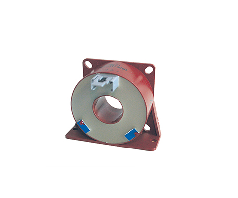
Passive Current Transformers Series IN-D
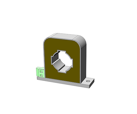
Differential current transformer Description The residual current transformer makes it possible to measure the residual current on single-phase or three-phase supply cables or individual lines. Both current-carrying conductors (forward and return conductors) are fed through the current opening of the current transformer. The current is measured by comparing the forward and return conductors. Any deviation is displayed at the output of the residual current transformer. Due to the use of highly permeable materials, a typical current deviation from 10 mA is given. The large opening allows the supply lines to pass directly through over a wide area, with the exception of the protective conductor. Due to the high current sensitivity, evaluation in several stages is possible: stage 1: Notice of a malfunction stage 2: Alarm stage 3: Switching off Advantages The measurement from 25 to 400 Hz Nanocrystalline core Transformer for measuring differential current High-quality UL-listed insulating materials (e.g., UL94VO) safe, electrically isolated primary and secondary circuits Robust housing designs (for horizontal/vertical mounting) Variable connections Wide range of housings with various push-through openings Residual current range 2 – 50 A Typical Applications Industry, Renewable energy sources, Metrology and testing techniquesEnergy, automation and building technology Technical data Type 2 4 8 29 30 40 30 40 50 Housing A Housing B Housing C Primary current [A] IPN 0,1 – 1 0,1 – 2 0,1 – 4 0,1 – 10 0,1 – 10 0,1 – 10 0,1 – 10 0,1 – 10 0,1 – 10 Max. Primary current [A] ImaxPN 2 4 8 20 30 40 30 40 50 Therm. Short-term current ITK 0,5 0,5 0,5 3,6 3,6 3,6 9 9 9 Secondary current [mA] IaN 2 4 4 20 10 5 20 16,67 10 Power [VA] Psek 0,004 0,008 0,016 0,030 0,030 0,015 0,06 0,05 0,06 Transformation ratio KN 500 500 1000 500 1000 2000 500 600 1000 Burden resistance [Ω] RB 1000 500 1000 75 300 600 150 180 600 Burden voltage [V] URB 2,0 2,0 4,0 1,5 3,0 3,0 3,0 3,0 6,0 Measuring accuracy 50 Hz [%] FU ≤ 1 ≤ 1 ≤ 1 ≤ 1 ≤ 1 ≤ 1 ≤ 1 ≤ 1 ≤ 1 Ambient temperature [°C] TA -10 to +50 -10 to +50 -10 to +50 -10 to +50 -10 to +50 -10 to +50 -10 to +50 -10 to +50 -10 to +50 Frequency range [Hz] f 25 to 400 25 to 400 25 to 400 25 to 400 25 to 400 25 to 400 25 to 400 25 to 400 25 to 400 Insulation test voltagePrimary / Secondary /2 sec [kVac] VP 3 3 3 3 3 3 3 3 3 Connection A Flat 6.3 x 0.8 / plug-in connectionMKS 1853 / terminal 1.5 mm² Storage temperature TS -25 to +85 -25 to +85 -25 to +85 -25 to +85 -25 to +85 -25 to +85 -25 to +85 -25 to +85 -25 to +85 Coil resistance RS 11 11 46 4,5 19 65 5,5 6,5 21 Weight m 0,068 0,068 0,070 0,278 0,278 0,290 0,280 0,280 0,290 Standards EN/IEC 61869-1/2 tracking resistance CTI Housing / cast resin 550/660M or 400/600M Creepage distance dCp 18 18 18 8 8 8 18 18 18 Clearance distance dCI 16 16 16 7 7 7 16 16 16 Dimensions in MM Type Housing PIN connection [mm²] h [mm] b1/b2 [mm] t [mm] DL/DL1 [mm] FS [mm] p/s [mm] a [mm] c [mm] f [mm] e [mm] l [mm] IN-D / 2 A 1 – 2 38 38/54 20 13 / – 6,3 x 0,8 – 30 47 4,8 – 9 IN-D / 4 A 1 – 2 38 38/54 20 13 / – 6,3 x 0,8 – 30 47 4,8 – 9 IN-D / 8 A 1 – 2 38 38/54 20 13 / – 6,3 x 0,8 – 30 47 4,8 – 9 IN-D / 20 B MKS1853 55 50/68 26 20,2 / – – 45 / 45 60 13 4,3 6 x 4,0 23 IN-D / 30 B MKS1853 55 50/68 26 20,2 / – – 45 / 45 60 13 4,3 6 x 4,0 23 IN-D / 40 B MKS1853 55 50/68 26 20,2 / – – 45 / 45 60 13 4,3 6 x 4,0 23 IN-D / 30 C Terminal 83 100/70 28 35 / 38 – 86 / – 14 – 7 – – IN-D / 40 C Terminal 83 100/70 28 35 / 38 – 86 / – 14 – 7 – – IN-D / 30 C Terminal 83 100/70 28 35 / 38 – 86 / – 14 – 7 – – Datasheet All data and configurations can be found in our product datasheet. Download Datasheet Certifications
PASSIVE CURRENT TRANSFORMER SERIES IE Pin Version
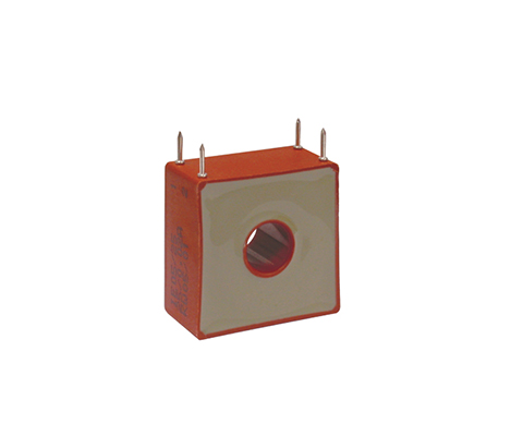
Through-hole current transformers (PIN version) Description With through-hole current transformers, the primary conductor on the construction side is inserted through the current transformer opening in the housing. The through-hole opening is oriented to the primary current strength. Wound current transformers have a primary winding and a secondary winding. Both windings are applied to the closed ring core and separated from each other by insulation. This principle is predominantly used for small primary currents. Advantages PIN – Connection according to UL 94 V0 Through-hole current transformers for direct conductor routing Design as wound transformer for small currents Ring band cores made of high-quality silicon iron Measurement in the lower frequency range 16 2/3 to 400Hz High core output power and high-quality insulation Electrically isolated primary and secondary circuits easy-to-install designs Variable connections e.g. terminals, plugs, flat plugs, stranded wires or PCB mounting Versatile housing options with different through-hole openings Technical data According to: EN/IEC 61869-1/2 Rated primary current: 1 – 50 A Frequency range: 50 – 400 Hz Rated primary current: 1 – 50 A Type 1 3 5 10 25 50 2 windings through-hole transformer Primary current [A] IPN 1 3 5 10 25 50 Max. Primary current [A] ImaxPN 1,2 3,6 6 12 30 60 Secondary current [mA] IaN 20 20 20 20 200 200 Power [VA] Psek 0,1 0,1 0,1 0,1 0,12 0,5 Transformation ratio KN 50 150 250 500 1000 1000 Burden resistance [Ω] RB 250 250 250 250 200 200 Burden voltage [V] URB 5 5 5 5 5 10 Measuring accuracy 50 Hz [%] FU ≤ 1 ≤ 1 ≤ 1 ≤ 1 ≤ 1 ≤ 1 Ambient temperature [°C] TA -25 to + 70 -25 to + 70 -25 to + 70 -25 to + 70 -25 to + 70 -25 to + 70 Frequency range [Hz] f 50 – 400 50 – 400 50 – 400 50 – 400 50 – 400 50 – 400 Insulation test voltage [kVac] VP 3 3 3 3 3 3 Connection [mm²] 3-4/2-1 3-4/2-1 3-4/2-1 3-4/2-1 NC/2-1 NC/2-1 Weight [kg] 0,05 0,05 0,05 0,05 0,05 0,07 Standards EN/IEC 61869-1/2 Dimensions in MM Type PIN connection [A] h [mm] b [mm] t [mm] DL [mm] s [mm] l [mm] a [mm] c [mm] IE/1 3-4/2-1 34 33 18 9 1,0 3,5 27,5 10 IE/3 3-4/2-1 34 33 18 9 1,0 3,5 27,5 10 IE/5 3-4/2-1 34 33 18 9 1,0 3,5 27,5 10 IE/10 3-4/2-1 34 33 18 9 1,0 3,5 27,5 10 IE/25 NC/2-1 34 33 18 9 1,0 3,5 27,5 10 IE/50 NC/2-1 38 38 20 13 1,0 6,5 30 10
PASSIVE CURRENT TRANSFORMER SERIES IB
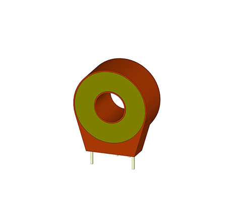
Current transformers for PCB mounting Description REO current transformers of the IB series are particularly well suited for mounting on printed circuit boards in the electronics sector of modern drive technology for control purposes and measured value acquisition. Advantages small space requirement PCB mounting according to UL 94 V0 Accuracy class 1 Measurement in the frequency range 50-400Hz low phase error for power measurement very low magnetic reversal and eddy current losses Electrically isolated primary and secondary circuits easy-to-install designs Technical data Type IB 0,5/5 IB 0,5/20 IB 0,5/40 Primary current [A] IPN 0 – 5 0 – 20 0 – 40 Max. Primary current [A] ImaxPN 7 25 50 Secondary current [mA] IaN 0 – 10 0 – 25 0 – 40 Power [VA] Psek 0 – 0,010 0 – 0,025 0 – 0,040 Translation ratio KN 1:500 1:800 1:1000 Burden resistance [Ω] RB 100 40 25 Burden voltage [V] URB 0 – 1 Measuring accuracy 50 Hz [%] FU ≤ 1 Ambient temperature [°C] TA 0..+85 Frequency range [Hz] f 50 – 400 Insulation test voltage [kVac] VP 3 Dimensions in MM Type Primary current [A] Height [mm] Width [mm] Depth [mm] Opening [mm] PIN thickness [mm] PIN length [mm] IB 05/5 0 – 5 30 26,5/17,5 14,5 10,5 0,7×0,7 5,0 IB 05/20 0 – 20 30 26,5/17,5 14,5 10,5 0,7×0,7 5,0 IB 05/40 0 – 40 30 26,5/17,5 14,5 10,5 0,7×0,7 5,0 Datasheet All data and configurations can be found in our product datasheet. Download Datasheet Certifications
Active Current Transformer Series WKO

Closed-loop current transformers Description Closed-loop current transformers The WKO current sensors work according to the proven compensation principle and are suitable for measuring direct, alternating and mixed currents. The primary current flow generates a magnetic flux, which is compensated by an internal secondary coil.The current evaluation is realized with an electronic circuit and a Hall sensor. The secondary compensation current is an exact reflection of the primary current to be measured. Unique Selling Point Measurement of direct, alternating and mixed currents Very high precision and short response time Broad frequency spectrum and low-temperature drift Very good linearity and overcurrent resistance No additional losses in the measuring circuit (DC to 150 kHz) Current output for lengthy transmission lines High-quality UL-listed insulating materials (e.g., UL94VO) Advantages (mechanical) Robust housing designs (for horizontal/vertical mounting) Variable connections, e.g. clamps, plugs, flat-cable plugs or cables versatile housing range with different Feed-through openings Typical Applications Industry, Renewable Energies, Railway Technology, Energy, Automation and Building Technology ELECTRICAL DATA Type WKO 25 WKO 50 WKO 100 WKO 300 WKO 500 WKO 1000 Primary RMS nominal current IPN [A] 25 50 100 300 500 1000 Measuring range IP [A] 0…±35 0…±70 0…±150 0…±500 0…±1000 0…±1500 Supply UC [V] ±12 …15 ±12 …15 ±12 …15 ±12 …15 ±12 …24 ±12 …24 Measuring accuracy XG@Ipn [-20…70°C] from IPN [%] > ±0,9 > ±1 > ±1 > ±1 > ±1 > ±1 Translation KN 1000 1000 1000 2000 5000 5000 Secondary RMS Nominal current ISN [mA] 25 50 100 150 100 200 Secondary winding Resistive sand RS@70°C [Ω] 16 43 24 30 72 48 Idle current [mA] 36+IS 11+IS 36+IS 36+IS 36+IS 24+IS Accuracy and dynamic data Type WKO 25 WKO 50 WKO 100 WKO 300 WKO 500 WKO 1000 Linearity error e [%] < ±0.1 < ±0.1 < ±0.1 < ±0.1 < ±0.1 < ±0.1 Offset error@25°CIO [mA] > 0,3 > 0,3 > 0,4 > 0,2 > 0,2 > 0,3 Offset Drift-25°C…+70°CIOT [mA] > 0,5 > 0,5 > 1 > 0,5 > 0,5 > 0,5 Response time tra[μs] > 0,5 > 0,5 > 0,5 > 0,5 > 0,5 > 0,5 Response time 10%-90% ta [μs] > 1 > 1 > 1 > 1 > 1 > 1 dl/dt ta [A/μs] > 50 > 50 > 100 > 100 > 100 > 100 Bandwidth -1 dB [kHz] DC…150 DC…200 DC…100 DC…100 DC…100 DC…100 Insulation data Type WKO 25 WKO 50 WKO 100 WKO 300 WKO 500 WKO 1000 Creepage distance dCp [mm] 4 8 10 10 10 15 Air section dCi[mm] 3 7 9 9 9 12 Leakage current resistance [CTI] 600 600 600 600 600 600 AC insulation test 50/60Hz 1min Ud [kV] 3,8 3,8 3,8 3,8 6 6 Pulse voltage test 1,2/50μs Ui[kV] 6 6 6 6 12,5 14,5 Mass [kg] 0,08 0,022 0,125 0,125 0,240 0,450 Dimensions in MM Type Pin connection/ 4-pin h [mm] b [mm] b1/b2 [mm] t [mm] DL [mm] p/s [mm] a/a1 [mm] c1/c2 [mm] f [mm] e [mm] l [mm] WKO 25 A; -U; +U 39 39 – 26 10 – 2 x 10/6,5 25/6,5 M3 6,0 x 4,0 9 WKO 50 A; -U; +U Please find in the drawing WKO 100 A; -U; +U 55 – 55/68 26 20,2 45/45 – 13,0/– 4,3 6,0×4,0 12 WKO 300 A; -U; +U 55 – 55/68 26 20,2 45/45 – 13,0/– 4,3 6,0×4,0 12 WKO 500 A; -U; +U 70 – 70/89 33 31,0 57/57 – 15,2/– 4,3 6,0×4,3 12 WKO 1000 A; -U; +U 95 – 94/110 44 40,0 78/78 – 18,0/– 5,3 8,0×5,3 12 Datasheet All data and configurations can be found in our product datasheet. Download Datasheet Certifications
ACTIVE CURRENT TRANSFORMER WDI SERIES
AC/DC Direct-Imaging Current Transformers (Open-Loop Converters) Description Direct-imaging current transformer (Open-Loop Converter) The WDI current sensor is a direct-imaging current transformer designed for measuring DC and AC currents. The primary current flow generates a magnetic flux, which is evaluated in the air gap by means of a magnetic circuit and Hall sensor. An electronic circuit processes the signal from the Hall sensor and outputs an exact image of the primary current with a voltage at the output. Advantages (Electrical) Measurement of DC and AC currents Voltage output low power consumption no additional losses in the measuring circuit high-quality insulation materials listed according to UL safe, electrically isolated primary and secondary circuits good value for money Advantages (Mechanical) low weight robust housing designs (horizontal/vertical mounting) Connections: terminals, plugs, flat connectors or cables Versatile housing options with different through-hole openings Typical Applications Industry, Renewable Energies, Railway Technology, Energy, Automation and Building Technology Technical data Type 25 150 300 Primary current [A] ÎPN Peak 25 150 300 Max. Primary current [A] ÎmaxPN Peak 0- ± 30 0- ± 180 0- ± 360 Secondary current [mA] ÎoutPN ± 5 ± 5 ± 5 Min. load resistance RBmin ± 15 Vdc ± 30A peak=2 ± 150 peak=2 ± 300 peak=2 ± 180A peak=2 ± 360A peak=2 Max. load resistance RBmax ± 15 Vdc ± 30A peak=10 ± 150 peak=2 ± 300 peak=2 ± 180A peak=2 ± 360A peak=2 Max. peak output voltage [V] ÜaN Peak ± 10 ± 10 ± 10 Operating voltage [Vdc] US ± 5% ± 15 ± 15 ± 15 No-load current [mA] IBO (@ ± 15 V) + loutpN 9 9 9 Insulation test voltage [kV] VP r.m.s. 50 Hz 3 3 3 Impulse withstand voltage[kV] VW 1,2/50μs 3 5 5 Measuring accuracy 50 Hz [%] FU @IPN, TA=25°C ± 0.6 ± 0.6 ± 0.6 Linearity error [%] FLU @TA=25°C ≤ 1.0 ≤ 1.0 ≤ 1.0 Offset voltage [mV] Uo @IPN = 0, TA = 25°C 20 20 20 Drift offset voltage [mV] △Uo Io -25°C…+70°C 60 60 60 Temperature drift [%K] %/△T ≤ 0.05 ≤ 0.05 ≤ 0.05 Response time [μs] tr @ 90% of IPN 25 25 25 Frequency range [kHz] f (-3 dB) DC … 10 (-3 dB) DC … 10 (-3 dB) DC … 10 Ambient temperature [°C] TA -25 to + 75 -25 to + 75 -25 to + 75 Storage temperature[°C] Ts -10 to + 85 -10 to + 85 -10 to + 85 Weight [kg] m 0,075 0,075 0,075 Creepage distance [mm] dCp 4 10 10 Clearance [mm] dCpi 3 9 9 Dimensions in MM Type PIN connection / 4-pin h [mm] b [mm] b1/b2 [mm] t [mm] DL [mm] p/s [mm] a/a1 [mm] c1/c2 [mm] f [mm] e [mm] l [mm] WDI 25 A; O,-U; +U 39 39 – 26,5 10 – 3 x 10/6,5 25/6,5 M4 – 9 WDI 150 A; O,-U; +U 55 – 55/68 26 20,2 45/45 60/– 13/– 4,3 6,0 x 4,0 23 WDI 300 A; O,-U; +U 55 – 55/68 26 20,2 45/45 60/– 13/– 4,3 6,0 x 4,0 23 Datasheet All data and configurations can be found in our product datasheet. Download Datasheet Certifications