
AC Magnets REOVIB WI 721
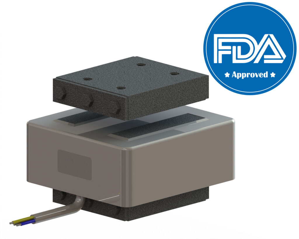
Powder-coated version Description Powder-coated version, fully encapsulated at 900 1/min, 1500 1/min, 3000 1/min or 6000 1/min, power ratings up to 3900 VA Mounting via threaded holes on the base and armature surface Cable version downwards with unshielded or shielded cables The use of a new coating technology allows us to design the vibrating magnet to be smaller in the WI 721 series. This results in significant savings in terms of weight, material and installation space. This optimized surface coating also ensures a consistently high performance, without the usual performance losses that can occur with other systems. The advantages of this new coating are numerous: Use in the pharmaceutical industry Use in the food processing industry with FDA conformity Corrosion protection High temperature resistance Non-flammable Cold resistant Homogeneous coating Solvent resistance High abrasion resistance Thanks to these properties, the WI 721 series is ideally suited for demanding applications, especially in environments that require high standards of hygiene, durability and performance. Advantages Corrosion protection through powder coating FDA-compliant (Food and Drug Administration) Optimum size/performance ratio Good adjustability Power ratings up to 3900 VA Also for low-frequency applications Peak tractive force up to 6900 N Flat designs Typical Applications Packaging and weighing industry for feeding and sorting processes, automation processes using drives with vibrating magnets, particularly suitable for the food and pharmaceutical industries (FDA-compliant) Technical data Types Max. nominal air gap[mm] Power at 6000 1/min [VA] Nominal current=thermal nominal current at 230V [A] Peak tractive force at nominal air gap [N] Power at 3000 1/min [VA] therm. Nominal current at 230V [A] Peak tractive force at nominal air gap [N] Weight magnet [kg] Weight armature [kg] REOVIB WI 721/10 2,5 320 1,4 230 280 1,2 229 2,1 0,34 REOVIB WI 721/12 3 450 1,95 330 425 1,85 318 2,8 0,62 REOVIB WI 721/14 3 1200 5,2 850 1200 5,2 1410 6,9 1,45 REOVIB WI 721/16 3 2200 9,5 1590 1890 8,2 2620 10,5 2,6 REOVIB WI 721/18 3 – – – 3900 16,9 6900 28 9 Dimensions in mm Types a b c d f1 f2 f3 g h i p r REOVIB WI 721/10 100 68 67 – 62,5 12,5 9 67 39 18,5 30 M6 REOVIB WI 721/12 100 100 67 40 62,5 15,5 9 67 71 18,5 30 M6 REOVIB WI 721/14 155 110 109 – 91,5 23,5 15 109 69 27,5 50 M10 REOVIB WI 721/16 155 168 109 80 91,5 23,5 15 109 127 27,5 50 M10 REOVIB WI 721/18 230 170 170 65 129,5 42,5 18 170 121 48,5 75 M12 Certifications
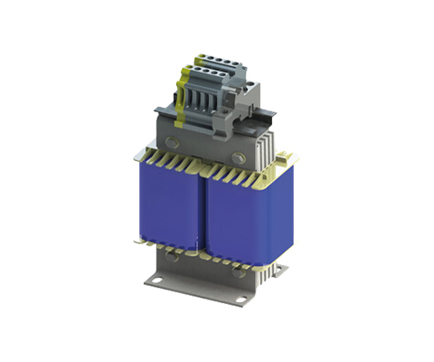
Isolating transformer REOMED I
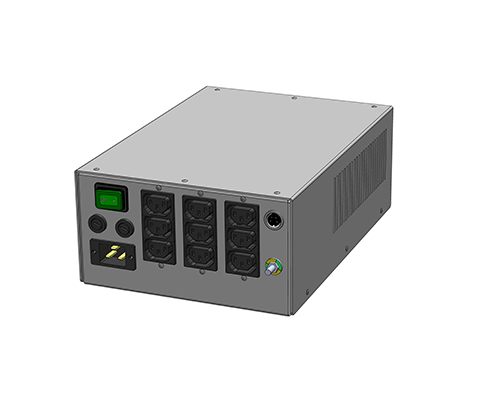
Medical systems must safely comply with the leakage currents specified in the standard.
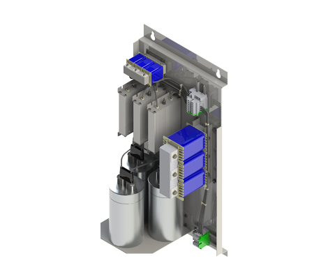
Isolating transformer REOMED II
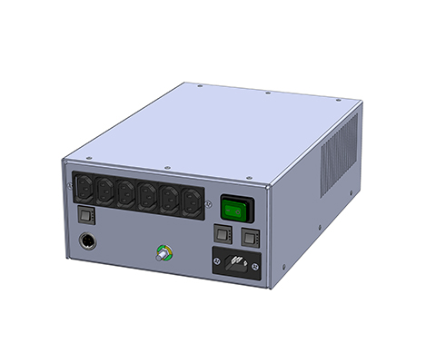
The REOMED II isolation transformer is a reliable leakage current limiter in medical systems.
Drossel LD-DH 100
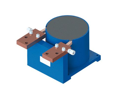
Directly cooled inrush current choke Description The short-circuit current limiting choke is used to limit the short-circuit current in the event of a bridge short circuit. This protects the intermediate circuit and prevents the IGBT from being destroyed. Advantages very little copper usage very small dimensions compared to the non-forced cooling version significantly lower weight to be cooled with water/glycol very high protection class also suitable for high pulse currents Technical data According to: EN 60076-6 Test voltage: 12kV Overload: 1,5 x INenn 1 min / h Climate category: DIN IEC 68 Part 1 25/085/21 Nominal voltage: 3000 V Nominal current: 500 – 2500 A
Test Choke RPD 9039

Three-phase load reactor Description Drive inverters or output filters must be tested at nominal current, a process typically performed using motor-generator sets. Due to the high costs, test specimens can alternatively be loaded with Chokes that offer sufficient linearity and do not exceed the temperature limit at higher frequencies. Advantages small dimensions Cost-effective solution Technical data Cooling: AN Insulation class F Climatic category: 25/085/21 DIN IEC 68 Part 1 Max. winding temperature: 140 °C Protection rating: IP 00 Rated voltage : 400 V Rated current : 0,6 – 75 A Inductance : 3,15 – 254 mH Type Rated voltage [V] Rated current [A] Inductance [mH] DC-Resistance [mΩ] Power loss [W] RPD 9039/0,6 3 x 400 0,6 254 6009,2 20 RPD 9039/7,0 3 x 400 7 31,4 221,7 70 RPD 9039/32,0 3 x 400 32 8,550 34,3 230 RPD 9039/75,0 3 x 400 75 3,150 12,6 430 Dimensions in MM Type L [mm] B [mm] H [mm] N1 [mm] N2 [mm] øD1 [mm] øD1 [mm] A1 [mm] Copper [kg] Weight [kg] RPD 9039/0,6 125 91 85 100 52 5 x 8 9 33,1 1 2 RPD 9039/7,0 190 123 157 170 79 8 x 12 9 34,5 3 10 RPD 9039/32,0 300 168 264 224 120 10 x 18 9 34,7 11 38 RPD 9039/75,0 360 182 313 264 142 10 x 18 9 35,7 18 58
Test reactor NPT 8929
Single-phase test reactor Description These chokes are used in test laboratories as load chokes. They can be interconnected (almost) arbitrarily. If these chokes are used with appropriate resistors, testing under various cos(phi) is possible. This is required, for example, to test the connection and switching behavior of components Advantages Robust design High flexibility compact design Low losses Technical data Insulation class: F at 40° C Climatic category: 25/085/21 DIN IEC 68 Part 1 Max. winding temperature: 125° C Protection class: IP00 Nominal Voltage: 230 V Rated current: 0,5 – 32,5 A Inductance: 0,127 – 3180 mH Type Rated voltage [V] Rated current [A] Inductance [mH] DC-Resistance [mΩ] Power loss [W] NPT 8929 / 0,5 230 0,5 3180 55670,2 23 NPT 8929 / 1,25 230 1,25 1270 16880,0 43 NPT 8929 / 1,66 230 1,66 955 9977, 8 47 NPT 8929 / 2,5 230 2,5 636 6388,5 66 NPT 8929 / 5 230 5,0 318 1782,5 94 NPT 8929 / 32,5 230 32,5 0,318 0,0 39 NPT 8929 / 32,5 230 32,5 0,127 7,0 13 NPT 8929 / 32,5 230 32,5 0,318 0,0 27 Dimensions in MM Type L [mm] B [mm] H [mm] N1 [mm] N2 [mm] øD1 [mm] Connection [mm²] Copper [kg] Weight [kg] NPT 8929 / 0,5 120 96 205 76 77 7 x 13 2,5 0,7 5 NPT 8929 / 1,25 160 105 265 100 81 7 x 13 2,5 2 9,8 NPT 8929 / 1,66 160 115 270 100 91 7 x 13 2,5 3,1 12,2 NPT 8929 / 2,5 200 122 310 124 94 10 x 18 4 3,9 17 NPT 8929 / 5 240 153 355 144 125 10 x 18 4 7,3 29 NPT 8929 / 32,5 120 96 208 76 77 7 x 13 16 0,84 6,5 NPT 8929 / 32,5 100 82 190 63 65 6 x 10 16 0,44 3,6 NPT 8929 / 32,5 120 96 208 76 77 7 x 13 16 0,94 6,5
Test Choke NPT 892
Single-Phase DC Test Choke Description Switches must pass many different tests during the approval phase. Some of these tests concern switching behavior under various load conditions; the switch is tested at nominal load, overload, and various power factors. In addition to continuous load, switch-on and switch-off processes are also examined. During these tests, it is crucial not to change the set parameters throughout the entire test. In the past, air-core chokes were used as inductive loads because they hardly saturate. However, air-core chokes are larger and have a stronger stray field than comparable iron-core chokes with equivalent magnetic energy. To adjust the respective cos? value, appropriately adapted Resistors then had to be connected. To meet all required test points, many different inductive and ohmic loads had to be available. Advantages Optimized linearity, thus no saturation in the respective operating range multiple taps, only a few Chokes are needed instead of many Optimized winding resistance, thereby reducing ohmic loads Designed for continuous and short-term load Optimization of weight and dimensions leads to cost reduction High nominal voltage, standard up to 1000V Technical data Insulation class: F at 40° C Climatic category: 25/085/21 DIN IEC 68 Part 1 Max. Winding Temperature: 100°C Protection rating: IP 00 Nominal Voltage: 24 V Nominal Current: 0.2 – 4 A Inductance: 160 – 125000 mH Type Rated voltage [V] Rated current [A] Inductance [mH] DC-Resistance [mΩ] Power loss [W] NPT 892/0.2 24 50/60 Hz 0,2 125.000 197,3 20 NPT 892/2 24 50/60 Hz 2 1.200 2,855 – NPT 892/4 24 50/60 Hz 4 160 2,8 64 Dimensions in MM Type L [mm] B [mm] H [mm] N1 [mm] N2 [mm] øD1 [mm] øD1 [mm] A1 [mm] Copper [kg] Weight [kg] NPT 892/0.2 200 148 261 124 120 10×18 6,2 24 1 2 NPT 892/2 240 168 375 144 140 10×18 18 44 3 10 NPT 892/4 280 173 417 176 143 13×20 4,4 38 11 38
Test Reactor NPT 8919

Single-phase iron core reactor Description These chokes are used as load chokes in testing laboratories. They can be interconnected (almost) arbitrarily. If these chokes are used with appropriate resistors, testing is possible under various cos(phi). This is required, for example, to test the connection and switch-on behavior of components. Advantages Robust design High flexibility compact design Low losses Technical data Insulation class: F at 40° C Climatic category: 25/085/21 DIN IEC 68 Part 1 Max. winding temperature: 125° C Protection class: IP00 Nominal voltage: 230 – 600 V Nominal current: 1.5 – 32.5 A Inductance: 0.031 – 71 mH Optional extras Also available as IP 54 with: Input cable/output cable Input cable/output socket Complete cable connection solution for mains, output and control connections
Harmonic Filter CNW 999

Compensation choke (7 or 14% detuning factor) Description Detuning (p) of reactive current and harmonic compensation systems; protection of the capacitors Advantages small inductance tolerance Low-noise linear behavior even with currents greater than the rated current optional connection via terminals or cable Technical data According to: DIN EN 61558-2-20 Test voltage: L-L 2100 V, DC 1 min L-PE 2700 V, DC 1 min Overload: 1,5 x INenn 1 min / h Climate category: DIN IEC 60068-1 Thermal class: H Protection class: IP00 Output voltage: 25 – 600 V Output current: 2 – 600 A Output power: 1000 – 15000 W Input voltage switchable: Input voltage switchable [V] V Type detuning factor 7% Reactive power capacitors [kVAr] Resonance frequency [Hz] Detuning factor (p) [%] Rated current [A] Current @ 50Hz [A] Inductance per strand [mH] Copper [kg] Weight [kg] CNW 999/10/6 6,25 189 7 10,6 10,0 6,0 3 8 CNW 999/19/3 12,5 189 7 20,5 19,0 3,0 4 9 CNW 999/38/1,53 25 189 7 41,0 38,0 1,53 1 17 CNW 999/75/0,78 50 189 7 80,0 75,0 0,78 1 28 Type detuning factor 14% Reactive power capacitors [kVAr] Resonance frequency [Hz] Detuning factor (p) [%] Rated current [A] Current @ 50Hz [A] Inductance per strand [mH] Copper [kg] Weight [kg] CNW 999/9/14,5 6,25 134 14 9,1 9,0 14,5 5 9 CNW 999/19/6,9 12,5 134 14 19,1 19,0 6,9 5 15 CNW 999/38/3,5 25 134 14 38,2 38,0 3,5 1 24 CNW 999/76/1,73 50 134 14 76,5 76,0 1,73 1 43 Dimensions in mm Type detuning factor 7% L [mm] B [mm] H [mm] N1 [mm] N2 [mm] D1 [mm] D2 [mm] Distance [mm] Weight [kg] CNW 999/10/6 190 101 155 170 69 8×12 – 30 7 CNW 999/19/3 190 111 155 170 79 8×12 – 30 8 CNW 999/38/1,53 240 150 205 185 97 10×18 9 55 17 CNW 999/75/0,78 265 172 225 200 122 10×18 9 55 28 Type detuning factor 14% L [mm] B [mm] H [mm] N1 [mm] N2 [mm] D1 [mm] D2 [mm] Distance [mm] Weight [kg] CNW 999/9/14,5 190 97 157 170 69 8×12 – 30 9 CNW 999/19/6,9 240 111 209 185 88 8×12 – 45 15 CNW 999/38/3,5 265 265 225 200 104 10×18 9 55 24 CNW 999/76/1,73 300 197 225 224 144 10×18 9 65 43
Harmonic Filter CNW 957
Regenerative harmonic filter (400V/50Hz) Description LCL filters are used in particular with regenerative converters (AFE), but also with converters for renewable energies. The main task of this filter is to eliminate the PWM frequencies, with the aim of not polluting the supply network when feeding in the energy. Advantages Increases the efficiency of your converter by improving the grid quality low losses save additional high energy costs compact design and light weight natural cooling optional charging resistor Technical data Nominal voltage: 3 x 400V / 50Hz Climatic category: 25/085/21 DIN IEC 68 Part 1 Ambient temperature: 40°C Protection class: IP00 optional: available with charging resistor Rated current: 14 – 74 A Frequency: 50 Hz Type Rated current [V] L [mm] B [mm] H [mm] N1 [mm] N2 [mm] D1 [mm] D2 [mm] Terminal [mm²] CNW 957 / 14 14 610 320 155 590 250 ø9 / ø17 ø7 4 CNW 957 / 29 29 610 320 225 590 250 ø9 / ø17 ø7 10 CNW 957 / 42 42 880 600 235 853 500 ø9 / ø17 ø9 16 CNW 957 / 74 74 880 600 235 853 500 ø9 / ø17 ø9 35