
Harmonic Filter CNW 8981 – 60 Hz (IP20)
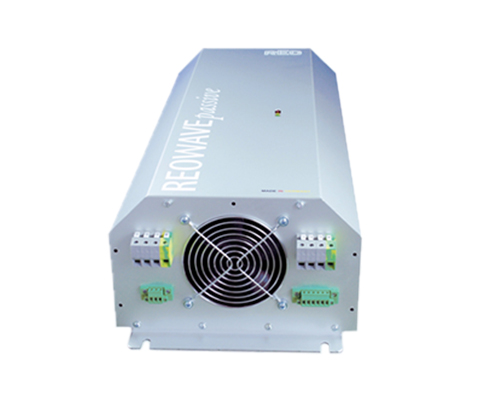
REOWAVEpassive – Harmonic Filter 60Hz/480 V (IP20) Description Reduce harmonic currents on the mains input side of inverters – save up to 30% energy costs. The REOWAVE®passive filters harmonic currents caused by B6 circuits (thyristor, diode bridge, etc.) and motor drives. The supply network is relieved by compensating for reactive harmonic power. This enables cost savings in material selection and energy consumption. Inrush currents and current peaks are strongly damped. This increases the lifespan and reliability of electrical systems. Thanks to its compact and ready-to-connect design, easy installation is possible even in existing systems. The REOWAVE®passive helps to comply with international power quality standards IEEE 519 or EN 61000-3. Advantages The REOWAVEpassive® can be ordered with the following additional options, in addition to the basic filter equipment: Traffic light function Temperature monitoring Potential-free signaling contacts Filter function shutdown in case of error Reduction of THDI value ≤ 5% Increase in grid stability Reduction of input current by up to 30% compact design Easy integration into existing systems Higher reliability of electrical systems Optional with overcurrent indicator for monitoring filter effectiveness The options are designed to help better control grid qualityand provide notifications to the control center in case of errors – giving you fullcontrol over your power consumption and simultaneously increasing operational safety. Technical data Rated voltage: 480V Frequency: 60Hz According to: EN 60289 / EN 61558 Test voltage: L-L 2500 V, DC 1min; L-PE 2500 V, DC 1min Insulation class: T40/F Protection class: IP20 Climate category: DIN IEC 60068-1 Protection class: IP20 (also available as IP00 version) Rated voltage: 480V / 60 Hz Standards: IEEE 519, EN 61000-3-12, EN 61000-3-2, IEC 61000-3-4 Image No. Type Rated current [A] Losses [W] Housing dimensions in mm Weight [kg] Terminal [mm²] L B H/H1 H2 N1 N2 D 4 CNW 8981/9 9 120 570 240 175 – 545 150 9 25 10 4 CNW 8981/12 12 120 570 240 175 – 545 150 9 30 10 5 CNW 8981/16 16 160 670 275 175 – 645 200 9 35 10 5 CNW 8981/22 22 230 670 275 175 – 645 200 9 40 10 5 CNW 8981/32 32 241 820 340 175 – 795 250 9 50 10 5 CNW 8981/36 36 300 820 340 175 – 795 250 9 50 10 6 CNW 8981/45 45 313 1000 360 260 – 925 298 13 65 16 6 CNW 8981/55 55 420 1000 360 260 – 925 298 13 65 16 6 CNW 8981/70 70 487 1000 360 260 – 925 298 13 80 16 7 CNW 8981/90 90 580 765 475 520 – 675 316 13 125 50 7 CNW 8981/110 110 710 765 475 520 – 675 316 13 175 50 7 CNW 8981/145 145 860 765 475 520 – 675 316 13 175 50 Image No. Type Rated current [A] Losses [W] Housing dimensions in mm Weight [kg] Terminal [mm²] L B H/H1 H2 N1 N2 D 8 CNW 8981/180 180 1000 600 600 1800 200 – – – 340 – 8 CNW 8981/200 200 1100 600 600 1800 200 – – – 345 – 8 CNW 8981/230 230 950 600 600 1800 200 – – – 352 – 8 CNW 8981/270 270 1140 600 600 1800 200 – – – 370 – 8 CNW 8981/330 330 1570 600 600 2000 200 – – – 427 – 8 CNW 8981/370 370 1680 600 600 2000 200 – – – 427 – 8 CNW 8981/400 400 1410 600 600 2000 200 – – – 442 – 8 CNW 8981/450 450 1500 600 600 2000 200 – – – 473 – 8 CNW 8981/550 550 1850 800 800 2000 200 – – – 540 – 8 CNW 8981/650 650 2090 800 800 2000 200 – – – 597 – Image No. Type Rated current [A] 9 CNW 8981/800 800 9 CNW 8981/1000 1000 9 CNW 8981/1200 1200 Due to the special design, a specific construction is required here – please contact us! *all variants also available as REOWAVE®passive Plus Datasheet All data and configurations can be found in our product datasheet. Download Datasheet
Harmonic Filter CNW 8981- 50 Hz
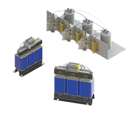
REOWAVE Passive – Harmonic Filter 50 Hz/400V (IP00) DESCRIPTION Reduce Harmonics – save up to 30% energy costs.The REOWAVE®passive filters harmonics caused by the B6 circuit (thyristor, diode bridge, etc.) and motor drives. The supply network is relieved by compensating the harmonics reactive power. This enables cost savings in material selection and energy consumption. Starting currents and current peaks are greatly attenuated.This increases the service life and reliability of electrical systems. Due to the compact and ready-build an easy installation is possible. The REOWAVE®passive helps to comply with international power quality standards IEEE 519 or EN 61000-3. ADVANTAGES Reduction of the THDI value Increasing network stability Reduction of the input current up to 30% Suitable for installation in control cabinets easy integration into existing systems Increased reliability of electrical installations TECHNICAL SPECIFICATION Nominal voltage: 400V Frequency: 50Hz According to: EN 60289 / EN 61558 Test voltage: LL 2500 V, DC 1min; L-PE 2500 V, DC 1min Insulation class: T40/F Climatic category: DIN IEC 60068-1 Protection: IP 00 (also available as IP20 version) Nominal voltage: 400V / 50 Hz Standards: IEEE 519, EN 61000-3-12, EN 61000-3-2, IEC 61000-3-4 TECHNICAL SPECIFICATION Image No. CNW type / Choke 1 / Choke 2 Rated current [A] Loss [W] Mains choke 1 [mm] L Mains choke 1 [mm] B1/B2 Mains choke 1 [mm] H Mains choke 1 [mm] N1 Mains choke 1 [mm] N2 Absorber circuit choke 2 [mm]L Absorber circuit choke 2 [mm]B Absorber circuit choke 2 [mm]H Suction Circuit Choke 2 [mm] N1 Absorber circuit choke 2 [mm] N2 Capacitors [mm]L Capacitors [mm]B Capacitors [mm]H Capacitors [mm]N1 Capacitors [mm]N2 Capacitors [mm]N3 Capacitors [mm]N4 Total weight (kg) [kg] 1/4 8981/6 6 95 190 82 210 170 58 125 85 125 100 55 500 200 100 450 470 100 – 12,5 1/4 8981/9 9 120 190 92 210 170 68 155 77 155 130 57 500 200 100 450 470 100 – 16,5 1/4 8981/12 12 120 190 92 210 170 68 155 92 185 130 72 500 260 230 450 470 100 – 17,5 2/4 8981/16 16 160 230 90 258 176 71 190 82 210 170 58 500 200 100 450 470 100 – 25 2/4 8981/22 22 230 230 114 260 176 95 190 82 210 170 58 500 350 100 450 470 100 125 31,4 2/4 8981/32 32 241 240 117 270 185 95 210 97 238 175 77 500 200 230 450 470 100 125 42,9 2/4 8981/36 36 300 240 132 270 185 109 210 97 238 175 77 500 200 230 450 470 100 125 42,5 1/4 8981/45 45 313 300 120 335 224 94 210 107 238 175 87 500 200 100 450 470 100 – 57,1 3/4 8981/55 55 420 300 152 330 224 119 210 117 238 175 97 500 350 200 450 470 100 125 59,8 3/4 8981/70 70 487 300 165 330 224 132 230 114 260 176 95 500 260 230 450 470 100 – 67,3 3/6 8981/90 90 580 360 193 330 264 167 230 114 263 176 95 500 260 100 450 470 100 – 81,8 3/6 8981/110 110 710 420 189 367 316 159 240 122 280 185 100 500 350 230 450 470 100 125 110,5 DIMENSIONS IN MM Image No. CNW type / Choke 1 / Choke 2 Rated current [A] Loss [W] Mains choke 1 [mm] L Mains choke 1 [mm] B1/B2 Mains choke 1 [mm] H Mains choke 1 [mm] N1 Mains choke 1 [mm] N2 Absorber circuit choke 2 [mm]L Absorber circuit choke 2 [mm]B Absorber circuit choke 2 [mm]H Suction Circuit Choke 2 [mm] N1 Absorber circuit choke 2 [mm] N2 Capacitors [mm]L Capacitors [mm]B Capacitors [mm]H Capacitors [mm]N1 Capacitors [mm]N2 Capacitors [mm]N3 Capacitors [mm]N4 Total weight (kg) [kg] 3/6 8981/145 145 860 420 204 369 316 174 265 133 270 200 103 500 350 230 450 470 100 125 130 3/6 8981/180 180 1000 420 234 368 316 204 300 135 315 224 107 500 260 200 450 470 100 – 160 3/6 8981/200 200 1100 420 234 369 316 204 300 150 280 224 120 500 260 400 450 470 100 – 167 3/6 8981/230 230 950 480 220 417 356 184 300 170 280 224 135 500 350 100 450 470 100 125 180 3/6 8981/270 270 1140 480 250 416 356 214 360 223 310 264 142 500 200 300 450 470 100 – 226 3/6 8981/330 330 1570 480 250 465 356 214 360 223 310 264 142 500 370 160 450 470 100 125 249 3/6 8981/370 370 1680 480 250 467 356 214 420 206 364 316 143 500 500 160 450 470 100 125 259 3/6 8981/400 400 1410 480 250 464 356 214 420 204 363 316 143 500 370 400 450 470 100 125 266 3/6 8981/450 450 1500 480 250 510 356 214 420 220 363 316 158 500 550 160 450 470 100 275 296 3/6 8981/550 550 1850 480 250 506 356 214 420 235 364 316 174 500 550 160 450 470 100 275 310 3/6 8981/90 650 2090 480 250 589 356 214 420 268 363 316 204 500 550 510 450 470 100 275 369 Image No. Type: CNW/ Choke1/ Choke2 Rated Current [A] Losses [W] 3/6 8981/800 800 2510 3/6 8981/1000 1000 2650 3/6 8981/1200 1200 3030 Due to the special design, a specific construction is required here – please contact us! *All variants are also available as REOWAVE®passive Plus Data sheet Download our extensive catalog and discover many other REO products. Download Datenblatt
Harmonic Filter CNW 897

Three-phase harmonic filter (400 V / 50/60 Hz) DESCRIPTION The filter is designed for the reduction of the THD (Total Harmonic Distortion) when used with B12 rectifiers. The harmonic currents are extremely suppressed so that the THD is reduced to lower than 5 % (for example in UPS-systems).Typical values of Total Harmonic Distortion with B12 rectifiers and the use of transformers are between 12 and 13%. This complies with the EN 61000-3-4 and EN 61000-3-12 standards.If more severe conditions for the mains are defined, in addition to the transformer it is necessary to use REO-Harmonic-Filter type CNW 897. These filters are available in two different versions: THD < <5% THD < <10 % The IP00 version is especially suitable for panel mounting and can be mounted to save space here. The CNW 897 helps to comply with international power quality standards IEEE 519 or EN 61000-3. ADVANTAGES Reduction of the THDI value Low voltage drop Increasing network stability Reduction of the input current up to 30% Suitable for installation in control cabinets easy integration into existing systems Increased reliability of electrical installations TECHNICAL SPECIFICATION According to: EN 60289 / EN 61558 Test voltage: L-L 2500 V, DC 1min; L-PE 2500 V, DC 1min Insulation class: T40/F Climatic category: DIN IEC 60068-1 Protection: IP 00 (also available as IP20 version) Nominal voltage: 400V / 50 Hz Standards: IEEE 519, EN 61000-3-12, EN 61000-3-2, IEC 61000-3-4 Type Rated voltage /Rated frequency [V] Rated current 3x [A] Inductance 3x [mH] Capacity capacitor [μF] Rated power [kVA] Power dissipation [W] Cu /AI [kg] Weight choke[kg] Weight capacitor[kg] CNW 897/25/400/5% 3×400 50/60 Hz 25 2,9 3 x 68 17,3 70 9/ 0 20 5,98 CNW 897/40/400/5% 3×400 50/60 Hz 40 2,48 3 x 80 27,7 90 11/ 0 26 6,58 CNW 897/70/400/5% 3×400 50/60 Hz 70 1,1 3 x 180 48,5 130 18/ 0 32 10,18 CNW 897/90/400/5% 3×400 50/60 Hz 90 0,9 3 x 220 62,4 200 0.8/ 3.4 49 12,58 CNW 897/120/400/5% 3×400 50/60 Hz 120 0,75 3 x 220 + 3 x 40 83,1 250 0.8/5.1 59 17,66 CNW 897/150/400/5% 3×400 50/60 Hz 150 0,6 3 x 330 103,9 350 1/ 8.4 59 16,78 CNW 897/180/400/5% 3×400 50/60 Hz 180 0,5 3 x 330 + 3 x 180 124,7 330 1.1/ 8.4 65 21,86 CNW 897/250/400/5% 3×400 50/60 Hz 250 0,36 3 x 330 + 3 x 220 173,2 440 1.7/ 12.8 82 29,33 CNW 897/310/400/5% 3×400 50/60 Hz 310 0,3 6 x 330 214,8 570 1.9 /14 95 33,53 CNW 897/400/400/5% 3×400 50/60 Hz 400 0,225 6 x 330 +3 x 220 277,1 910 3 / 10.1 108 45,2 CNW 897/600/400/5% 3×400 50/60 Hz 600 0,2 9 x 330 415,7 1040 6.4 / 22.8 193 49,4
EMI-Filter CNW 174

DC filter for photovoltaik (2 lines) DESCRIPTION Due to the increasingly efficient energy conversion in modern inverters, more and more high-frequency energies are being introduced into the DC circuits. These are caused by the fast switching processes of modern power semiconductors and can lead to premature aging of the solar modules. This results in a very high interference level in the frequency range of 150kHz – 30 MHz on both the AC and DC sides. This circumstance is not currently covered by standards for the DC side. The connected long DC cabling and the large-area PV modules represent a special feature that distinguishes inverters from all other electronic devices. The PV generator and the often very long DC cables function as antennae and can radiate originally conducted interference.The electromagnetic compatibility of the inverters to other devices is guaranteed. ADVANTAGES compact construction protection of solar cells from high frequency designed to conform to existing and planned quick connection low-temperature rise optional anti-surge protection universal protection for all inverters TYPICAL APPLICATIONS Applications: The DC-filter surpresses grid-bound troubles of inverters for renewable energies like solar and wind power. TECHNICAL SPECIFICATION Conforming to: VDE 0565-3/ IEC 950/ UL 1283 Test voltage: L-L 3000 V, DC 1 s; L-PE 3000 V, DC 1s Climatic category: DIN IEC 60068-1 Overload: 1,5 x INenn 1 min / h Nominal Voltage: 900 V Rated current: 10 – 600 A Type Rated voltage [V] Rated current [A] Leakage current [A][mA] Typical inverter power [kW] Power loss [W] CNW 174/150 900 V DC 150 <30 60 32 CNW 174/250 900 V DC 250 <30 100 10 CNW 174/400 900 V DC 400 <30 150 16 CNW 174/600 900 V DC 600 <30 250 28
EMI-Filter CNW 173
DC filter for photovoltaik (2 lines) DESCRIPTION As a result of the ever more efficient energy conversion in modern power inverters, ever more high-frequency energy is being introduced into DC circuits. This energy is caused by the quick switching operations of modern power semi-conductors and could cause the premature aging of solar modules. REO-DC mains filters work in both directions. In practical usage, this means that the end devices are protected against unnecessary high frequencies. On the other side however, the power network is also protected against the spreading of self-generated high frequencies by the end devices. In the frequency range of 150kHz – 30MHz, a very high interference level occurs on both the AC and DC sides. This circumstance is not currently addressed in the standards for the DC side. The connected long DC cabling and the large-area PV modules represent a unique feature that distinguishes inverters from all other electronic devices. The PV generator and the often very long DC lines act as antennas and can radiate originally conducted interference. The electromagnetic compatibility of inverters with other devices must be ensured. ADVANTAGES compact construction protection of solar cells from high frequency designed to conform to existing and planned quick connection low-temperature rise optional anti-surge protection Optionally with DC current sensors universal protection for all inverters TYPICAL APPLICATIONS The DC-filter suppresses grid-bound troubles of inverters for renewable energies like solar and wind power. TECHNICAL SPECIFICATION Conforming to: VDE 0565-3/ IEC 950/ UL 1283 Test voltage: L-L 3000 V, DC 1 s; L-PE 3000 V, DC 1s Climatic category: DIN IEC 60068-1 Overload: 1,5 x INenn 1 min / h Nominal voltage: 1000 V Rated current: 25 A Type Rated voltage [V] Rated current [A] Leakage current [mA] Typical inverter power [kW] Power loss [W] CNW 173/250 1000 V DC 250 <30 100 10 CNW 173/400 1000 V DC 400 <30 150 16 CNW 173/600 1000 V DC 600 <30 250 28 CNW 173/800 1000 V DC 800 <30 350 28 CNW 173/1000 1000 V DC 1000 <30 400 35 CNW 173/1300 1000 V DC 1300 <30 400 35
EMI-Filter N CNW 114

EMI-Filter N CNW 114 Three-phase line filter with increased attenuation, 3 lines DESCRIPTION When assembling electronic components in a control cabinet, the same circuits are often required with different power ratings. To avoid having to change the drilling pattern each time, it is ideal to combine multiple power ranges. The filters in this series have identical mounting dimensions in the most important power range, allowing the filters to be interchanged. ADVANTAGES Small dimensions quick connection low-temperature rise touch-proof terminals Very good attenuation performance across a wide frequency spectrum IT-versions possible TYPICAL APPLICATIONS Frequency converters for motor drives, wind power installations and power supply units TECHNICAL SPECIFICATION Conforming to: VDE 0565-3 / IEC 950 / UL 1283 Test voltage: L-L 2100 V, DC 1s, L-PE 2700 V, DC 1s Overload: 1,5 x I 1 min/h Climatic category: DIN IEC 68 Part 1 25/085/21 Type Rated voltage [V] Rated current [A] Leakage current [A][mA] Cx [μF] Cy nF] L [mH] R [kOhm] Frequency[Hz] N CNW 114/8 3×500* 8 <5 1,0 0,244 7,6 1,12 50/60 N CNW 114/16 3×500* 16 <30 2,53 1,57 5,2 1,12 50/60 N CNW 114/25 3×500* 25 <30 2,53 1,57 2,5 1,12 50/60 N CNW 114/36 3×500* 36 <30 2,53 1,57 1,5 1,12 50/60 N CNW 114/50 3×500* 50 <30 2,53 1,57 0,9 1,12 50/60 N CNW 114/64 3×500* 64 <30 2,53 1,57 0,9 1,12 50/60 N CNW 114/80 3×500* 80 <35 3,63 1,68 0,8 1,12 50/60 N CNW 114/110 3×500* 110 <35 3,63 1,68 0,5 1,12 50/60 N CNW 114/180 3×500* 180 <35 3,63 1,68 0,5 1,12 50/60 N CNW 114/300 3×500* 300 <60 7,26 3,36 0,3 1,12 50/60 N CNW 114/450 3×500* 450 <60 7,26 3,36 0,16 1,12 50/60 N CNW 114/600 3×500* 600 <60 7,26 3,36 0,155 1,12 50/60 N CNW 114/900 3×500* 900 <60 7,26 3,36 0,055 1,12 50/60 N CNW 114/1200 3×500* 1200 <60 7,26 3,36 0,055 1,12 50/60 *Also available with 690V upon request. Also available as a variant with cULus certification. Upon request, we will gladly send you the corresponding data sheet. DIMENSIONS IN MM Type Housing Connection PE-Connection B1[mm] B2[mm] B3[mm] D1[mm] D2[mm] H[mm] L1[mm] L2[mm] L3[mm] N CNW 114/8 B Clamps 4mm² 2 x M6 98 80 70 5 – 70 177 150 90 N CNW 114/16 B Clamps 4mm² 2 x M6 148 135 120 7 – 70 227 200 160 N CNW 114/25 B Clamps 6mm² 2 x M6 148 135 120 7 – 70 229 200 160 N CNW 114/36 B Clamps10mm² 2 x M6 148 135 120 7 – 70 229 200 160 N CNW 114/50 B Clamps16mm² 2 x M6 148 135 120 7 – 70 238 200 160 N CNW 114/64 B Clamps16mm² 2 x M6 148 135 120 7 – 70 238 200 160 N CNW 114/80 B Clamps 25mm² 2 x M10 168 155 140 7 – 90 303 240 160 N CNW 114/110 B Clamps 50mm² 2 x M12 168 155 140 7 – 90 331 240 160 N CNW 114/180 B Clamps 95mm² 2 x M12 168 155 140 7 – 90 339 240 160 N CNW 114/300 C Connecting bolt (M12) 1 x M10 265 250 230 7 – 130 438 348 180 N CNW 114/450 D Copper bus bar (25×8) 1 x M12 265 240 215 9 10,5 160 530 440 190 N CNW 114/600 D Copper bus bar (30×10) 1 x M12 265 240 215 9 10,5 160 550 440 190 N CNW 114/900 D Copper bus bar (50×10) 1 x M12 265 240 215 9 14 160 630 440 190 N CNW 114/1200 D Copper bus bar (60×10) 1 x M12 265 240 215 9 14 160 630 440 190 Data sheet Download our extensive catalog and discover many other REO products. Download Datenblatt Certifications
EMI-Filter CNW 107.3/690
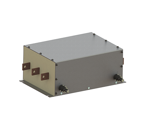
EMI-Filter CNW 107.3/690 High-current filter, 3-wire DESCRIPTION The EMI filter is specifically for the suppression of high-current applications in wind energy and industrial applications designed. This filter series is for the voltage levels of 480V and 690V constructed. The filter can be delivered in various casing versions. So it can be adapted to different environmental conditions.There are also versions for offshore applications possible. ADVANTAGES specifically designed for high performances suitable for offshore applications compact design Good heat dissipation rail connector fast installation TYPICAL APPLICATIONS The EMC filter is specifically for the suppression of high-current applications in wind energy and industrial applications designed. TECHNICAL SPECIFICATION Conforming to: VDE 0565-3 / IEC 950 / UL 1283 Test voltage: L-L 2100 V, DC 1s, L-PE 2700 V, DC 1s Overload: 1,5 x I 1 min/h Climatic category: DIN IEC 68 Part 1 25/085/21 Type Rated voltage [V] Rated current [A] Leakage current[mA] L[μF] Cx[μF] Cy[μH] CNW 107.3/280 3×480/ 690 3×280 <300 100 40 3,8 CNW 107.3/500 3×480/ 690 3×500 <300 100 40 3,8 CNW 107.3/700 3×480/ 690 3×700 <300 100 40 3,8 CNW 107.3/1000 3×480/ 690 3×1000 <300 100 40 3,8 CNW 107.3/1600 3×480/ 690 3×1600 <300 44 50 7,6 CNW 107.3/2500 3×480/ 690 3×2500 <300 44 50 7,6 CNW 107.3/3000 3×480/ 690 3×3000 <300 40 50 7,6 DIMENSIONS IN MM Type Connection PE-Connection L1[mm] L2[mm] L3[mm] L4[mm] B1[mm] B2[mm] H1[mm] CNW 107.3/280 30×5 M12 420 335 320 296 220 175 135 CNW 107.3/500 40×5 M12 420 335 320 296 220 175 135 CNW 107.3/700 40×10 M12 420 335 320 296 220 175 135 CNW 107.3/1000 40×10 M12 420 335 320 296 220 175 135 CNW 107.3/1600 50×10 M12 590 406 340 360 330 300 180 CNW 107.3/2500 80×15 M12 590 406 340 360 330 300 180 CNW 107.3/3000 120×15 M12 700 506 400 420 390 360 240 Data sheet Download our extensive catalog and discover many other REO products. Download Datenblatt Certifications
EMI-Filter CNW 107.3/690 and CNW 107.3/480
EMI-Filter N CNW 103 High-current line filter (3 conductors) DESCRIPTION The EMI filter is specifically for the suppression of high-current applications in wind energy and industrial applications designed. This filter series is for the voltage levels of 480V and 690V constructed. The filter can be delivered in various casing versions. So it can be adapted to different environmental conditions.There are also versions for offshore applications possible. ADVANTAGES specifically designed for high performances suitable for offshore applications compact design Good heat dissipation rail connector fast installation TYPICAL APPLICATIONS The EMI filter is specifically for the suppression of high-current applications in wind energy and industrial applications designed. TECHNICAL SPECIFICATION Conforming to: VDE 0565-3 / IEC 950 / UL 1283 Test voltage: L-N 2100 V,DC 1s, L/N-PE 2700 V,DC 1s Overload: 1,5 x I 1 min/h Climatic category: DIN IEC 68 Part 1 25/085/21 Rated voltage: 480 V Rated current: 280 – 3000 A Type Rated voltage [V] Rated current [A] Leakage current[mA] L[μF] Cx[μF] Cy[μH] CNW 107.3/280 3×480/ 690 3×280 <300 100 40 3,8 CNW 107.3/500 3×480/ 690 3×500 <300 100 40 3,8 CNW 107.3/700 3×480/ 690 3×700 <300 100 40 3,8 CNW 107.3/1000 3×480/ 690 3×1000 <300 100 40 3,8 CNW 107.3/1600 3×480/ 690 3×1600 <500 44 50 7,6 CNW 107.3/2500 3×480/ 690 3×2500 <500 44 50 7,6 CNW 107.3/3000 3×480/ 690 3×3000 <500 40 50 7,6 DIMENSIONS IN MM Type Connection PE-Connection L1[mm] L2[mm] L3[mm] L4[mm] B1[mm] B2[mm] L1[mm] L2[mm] L3[mm] CNW 107.3/280 30×5 M12 420 335 320 296 220 175 135 100 90 CNW 107.3/500 40×5 M12 420 335 320 296 220 175 135 100 90 CNW 107.3/700 40×10 M12 420 335 320 296 220 175 135 100 90 CNW 107.3/1000 40×10 M12 420 335 320 296 220 175 135 150 90 CNW 107.3/1600 50×10 M12 590 406 340 360 330 300 180 150 90 CNW 107.3/2500 80×15 M12 590 406 340 360 330 300 180 200 160 CNW 107.3/3000 120×15 M12 700 506 340 420 390 300 240 200 160 Data sheet Download our extensive catalog and discover many other REO products. Download Datenblatt Certifications
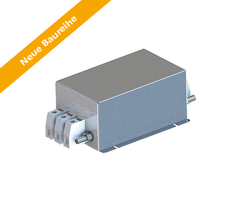
EMV Filter N CNW 105

Three-phase line filters (4 lines, single stage) (3A – 150A) DESCRIPTION NEW SERIES! The new series not only scores points for its faster delivery time, but also for its resource conservation and increased efficiency. Recommended filter for interference suppression according to EN 55011, Class A and EN 61800-3, Category C2. By using a REO three-phase line filter CNW 105 the noise level is reduced below the prescribed maximum value.REO line filters are suitable for individual and collective suppression. For collective suppression: As long as the rated current for each phase remains below the permissible extent, multiple devices can be suppressed. ADVANTAGES Small dimensions quick connection low-temperature rise touch-proof terminals good damping performance ata low leakage current TYPICAL APPLICATIONS Power supply units for data systems engineering, telecommunications, medical equipment and industrial applications TECHNICAL SPECIFICATION Conforming to: VDE 0565-3 / IEC 950 / UL 1283 Test voltage: L-L 2100 V, DC 1s, L-PE 2700 V, DC 1s Overload: 1,5 x I 1 min/h Climatic category: DIN IEC 68 Part 1 25/085/21 Type Rated voltage [V] Rated current [A] Leakage current [A][mA] Cx [μF] Cy nF] L [mH] R [MOhm] Frequency[Hz] N CNW 105/3 3×500 4×3 <1 0,5 30 4,0 1,12 50/60 N CNW 105/6 3×500 4×6 <1 0,5 30 2,4 1,12 50/60 N CNW 105/10 3×500 4×10 <1 0,5 30 1,0 1,12 50/60 N CNW 105/16 3×500 4×16 <1 1 43 1,6 1,12 50/60 N CNW 105/25 3×500 4×25 <1 1 43 1,4 1,12 50/60 N CNW 105/36 3×500 4×36 <1 2,2 44 1,2 1,12 50/60 N CNW 105/50 3×500 4×50 <1 2,2 44 0,75 1,12 50/60 N CNW 105/80 3×500 4×80 <3,5 3,3 111 0,5 1,12 50/60 N CNW 101/120 3×500 4×120 <3,5 3,3 111 0,36 1,12 50/60 CNW 105/150 3×500 4×150 <3,5 3,3 111 0,36 1,12 50/60 DIMENSIONS IN MM Type Housing Connection PE-Connection B1[mm] B2[mm] B2[mm] D[mm] H[mm] L1[mm] L2[mm] L3[mm] CNW 105/3 A Flat plug 6,3 mm AMP flat plug 53 – – 5,3 40 110 100 90 CNW 105/6 A Flat plug 6,3 mm AMP flat plug 53 – – 5,3 40 110 100 90 CNW 105/10 A Flat plug 6,3 mm AMP flat plug 53 – – 5,3 40 110 100 90 CNW 105/16 B Clamps 4mm² Earthing bolt (M6) 98 80 70 5,0 70 177 150 90 CNW 105/25 B Clamps 6mm² Earthing bolt (M6) 98 80 70 5,0 70 179 150 90 CNW 105/36 B Clamps10mm² Earthing bolt (M6) 148 135 120 7,0 70 269 240 160 CNW 105/50 B Clamps 25mm² Earthing bolt (M6) 148 135 120 7,0 70 278 240 160 CNW 105/80 B Clamps 25mm² Earthing bolt (M10) 168 155 140 7,0 90 303 240 160 CNW 105/120 B Clamps 50mm² Earthing bolt (M12) 168 155 140 7,0 90 331 240 160 CNW 105/150 B Clamps 50mm² Earthing bolt (M12) 168 155 140 7,0 90 331 240 160 Data sheet Download our extensive catalog and discover many other REO products. Download Datenblatt Certifications
EMC Filter N CNW 103
Three-phase mains filters (3 lines, single-stage) DESCRIPTION NEW SERIES! The new series not only scores points for its faster delivery time, but also for its resource conservation and increased efficiency. Recommended filter for suppressing interference according to EN 55011, Class A and EN 61800-3, category C2. Special installation Special connections For space and for assembly reasons it may be reasonable to use connections other than terminals. If the filter is always fitted in the same place, REO can build your individual filter-whether with bolts, cable or other connections. ADVANTAGES compact construction easy installation low-temperature rise touch-proof terminals good damping performance ata low leakage current useable for industrial applications Typical applications Frequency converters for motor drives (e.g. lifts, materials handling, pumps, ventilation and air-conditioning systems, industrial applications, wind power installations and power supply units Technical specifications Conforming to: VDE 0565-3 / IEC 950 / UL 1283 Test voltage: L-L 2100 V, DC 1s, L-PE 2700 V, DC 1s Overload: 1,5 x I 1 min/h Climatic category: DIN IEC 68 Part 1 25/085/21 Type Nominal voltage [V] Rated current [A] Leakage current [A][mA] Cx [μF] Cy [nF] L [mH] R [kOhm] Frequency[Hz] CNW 103/3 3×500 3×3 <1 0,5 30 3,0 1,12 50/60 Hz CNW 103/6 3×500 3×6 <1 0,5 30 2,2 1,12 50/60 Hz CNW 103/10 3×500 3×10 <1 0,5 30 1,7 1,12 50/60 Hz N CNW 103/16 3×500 3×16 <<1 1,0 39 1,5 1,12 50/60 Hz N CNW 103/25 3×500 3×25 <1 1,0 39 1,2 1,12 50/60 Hz N CNW 103/36 3×500 3×36 <1,5 2,2 60 1,5 1,12 50/60 Hz N CNW 103/50 3×500 3×50 <1,5 2,2 60 0,9 1,12 50/60 Hz N CNW 103/80 3×500 3×80 <5 2,75 197 0,4 1,12 50/60 Hz N CNW 103/120 3×500 3×120 <5 2,75 197 0,25 1,12 50/60 Hz N CNW 103/150 3×500 3×150 <5 2,75 197 0,8 1,12 50/60 Hz N CNW 103/180 3×500 3×180 <5 2,75 197 0,8 1,12 50/60 Hz DIMENSIONS IN MM Type Casing Connection PE-Connection B1[mm] B2[mm] B2[mm] D[mm] H[mm] L1[mm] L2[mm] L3[mm] CNW 103/3 A Flat plug 6,3 mm AMP flat plug 53 – – 5,3 40 110 100 90 CNW 103/6 A Flat plug 6,3 mm AMP flat plug 53 – – 5,3 40 110 100 90 CNW 103/10 A Flat plug 6,3 mm AMP flat plug 53 – – 5,3 40 110 100 90 N CNW 103/16 B Clamps 4mm² Earthing bolt (M6) 98 80 70 5,0 70 177 150 90 N CNW 103/25 B Clamps 6mm² Earthing bolt (M6) 98 80 70 5,0 70 179 150 90 N CNW 103/36 B Clamps10mm² Earthing bolt (M6) 148 135 120 7,0 70 229 200 160 N CNW 103/50 B Clamps16mm² Earthing bolt (M6) 148 135 120 7,0 70 238 200 160 N CNW 103/80 B Clamps 25mm² Earthing bolt (M10) 168 155 140 7,0 90 303 240 160 N CNW 103/120 B Clamps 50mm² Earthing bolt (M12) 168 155 140 7,0 90 331 240 160 N CNW 103/150 B Clamps 50mm² Earthing bolt (M12) 168 155 140 7,0 90 331 240 160 N CNW 103/180 B Clamps 95mm² Earthing bolt (M12) 168 155 140 7,0 90 339 240 160 Data sheet Download Datenblatt Certifications