
Passive Current Transformers Series IN-D
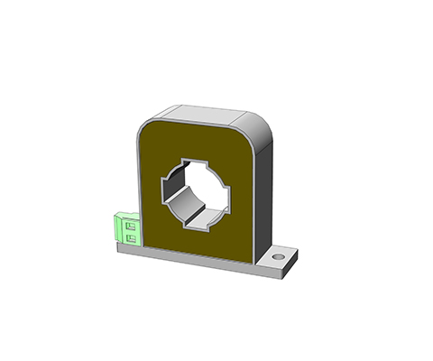
Differential current transformer Description The residual current transformer makes it possible to measure the residual current on single-phase or three-phase supply cables or individual lines. Both current-carrying conductors (forward and return conductors) are fed through the current opening of the current transformer. The current is measured by comparing the forward and return conductors. Any deviation is displayed at the output of the residual current transformer. Due to the use of highly permeable materials, a typical current deviation from 10 mA is given. The large opening allows the supply lines to pass directly through over a wide area, with the exception of the protective conductor. Due to the high current sensitivity, evaluation in several stages is possible: stage 1: Notice of a malfunction stage 2: Alarm stage 3: Switching off Advantages The measurement from 25 to 400 Hz Nanocrystalline core Transformer for measuring differential current High-quality UL-listed insulating materials (e.g., UL94VO) safe, electrically isolated primary and secondary circuits Robust housing designs (for horizontal/vertical mounting) Variable connections Wide range of housings with various push-through openings Residual current range 2 – 50 A Typical Applications Industry, Renewable energy sources, Metrology and testing techniquesEnergy, automation and building technology Technical data Type 2 4 8 29 30 40 30 40 50 Housing A Housing B Housing C Primary current [A] IPN 0,1 – 1 0,1 – 2 0,1 – 4 0,1 – 10 0,1 – 10 0,1 – 10 0,1 – 10 0,1 – 10 0,1 – 10 Max. Primary current [A] ImaxPN 2 4 8 20 30 40 30 40 50 Therm. Short-term current ITK 0,5 0,5 0,5 3,6 3,6 3,6 9 9 9 Secondary current [mA] IaN 2 4 4 20 10 5 20 16,67 10 Power [VA] Psek 0,004 0,008 0,016 0,030 0,030 0,015 0,06 0,05 0,06 Transformation ratio KN 500 500 1000 500 1000 2000 500 600 1000 Burden resistance [Ω] RB 1000 500 1000 75 300 600 150 180 600 Burden voltage [V] URB 2,0 2,0 4,0 1,5 3,0 3,0 3,0 3,0 6,0 Measuring accuracy 50 Hz [%] FU ≤ 1 ≤ 1 ≤ 1 ≤ 1 ≤ 1 ≤ 1 ≤ 1 ≤ 1 ≤ 1 Ambient temperature [°C] TA -10 to +50 -10 to +50 -10 to +50 -10 to +50 -10 to +50 -10 to +50 -10 to +50 -10 to +50 -10 to +50 Frequency range [Hz] f 25 to 400 25 to 400 25 to 400 25 to 400 25 to 400 25 to 400 25 to 400 25 to 400 25 to 400 Insulation test voltagePrimary / Secondary /2 sec [kVac] VP 3 3 3 3 3 3 3 3 3 Connection A Flat 6.3 x 0.8 / plug-in connectionMKS 1853 / terminal 1.5 mm² Storage temperature TS -25 to +85 -25 to +85 -25 to +85 -25 to +85 -25 to +85 -25 to +85 -25 to +85 -25 to +85 -25 to +85 Coil resistance RS 11 11 46 4,5 19 65 5,5 6,5 21 Weight m 0,068 0,068 0,070 0,278 0,278 0,290 0,280 0,280 0,290 Standards EN/IEC 61869-1/2 tracking resistance CTI Housing / cast resin 550/660M or 400/600M Creepage distance dCp 18 18 18 8 8 8 18 18 18 Clearance distance dCI 16 16 16 7 7 7 16 16 16 Dimensions in MM Type Housing PIN connection [mm²] h [mm] b1/b2 [mm] t [mm] DL/DL1 [mm] FS [mm] p/s [mm] a [mm] c [mm] f [mm] e [mm] l [mm] IN-D / 2 A 1 – 2 38 38/54 20 13 / – 6,3 x 0,8 – 30 47 4,8 – 9 IN-D / 4 A 1 – 2 38 38/54 20 13 / – 6,3 x 0,8 – 30 47 4,8 – 9 IN-D / 8 A 1 – 2 38 38/54 20 13 / – 6,3 x 0,8 – 30 47 4,8 – 9 IN-D / 20 B MKS1853 55 50/68 26 20,2 / – – 45 / 45 60 13 4,3 6 x 4,0 23 IN-D / 30 B MKS1853 55 50/68 26 20,2 / – – 45 / 45 60 13 4,3 6 x 4,0 23 IN-D / 40 B MKS1853 55 50/68 26 20,2 / – – 45 / 45 60 13 4,3 6 x 4,0 23 IN-D / 30 C Terminal 83 100/70 28 35 / 38 – 86 / – 14 – 7 – – IN-D / 40 C Terminal 83 100/70 28 35 / 38 – 86 / – 14 – 7 – – IN-D / 30 C Terminal 83 100/70 28 35 / 38 – 86 / – 14 – 7 – – Datasheet All data and configurations can be found in our product datasheet. Download Datasheet Certifications
PASSIVE CURRENT TRANSFORMER SERIES IE Pin Version
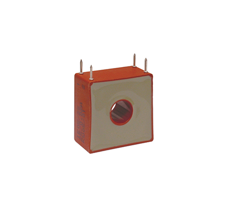
Through-hole current transformers (PIN version) Description With through-hole current transformers, the primary conductor on the construction side is inserted through the current transformer opening in the housing. The through-hole opening is oriented to the primary current strength. Wound current transformers have a primary winding and a secondary winding. Both windings are applied to the closed ring core and separated from each other by insulation. This principle is predominantly used for small primary currents. Advantages PIN – Connection according to UL 94 V0 Through-hole current transformers for direct conductor routing Design as wound transformer for small currents Ring band cores made of high-quality silicon iron Measurement in the lower frequency range 16 2/3 to 400Hz High core output power and high-quality insulation Electrically isolated primary and secondary circuits easy-to-install designs Variable connections e.g. terminals, plugs, flat plugs, stranded wires or PCB mounting Versatile housing options with different through-hole openings Technical data According to: EN/IEC 61869-1/2 Rated primary current: 1 – 50 A Frequency range: 50 – 400 Hz Rated primary current: 1 – 50 A Type 1 3 5 10 25 50 2 windings through-hole transformer Primary current [A] IPN 1 3 5 10 25 50 Max. Primary current [A] ImaxPN 1,2 3,6 6 12 30 60 Secondary current [mA] IaN 20 20 20 20 200 200 Power [VA] Psek 0,1 0,1 0,1 0,1 0,12 0,5 Transformation ratio KN 50 150 250 500 1000 1000 Burden resistance [Ω] RB 250 250 250 250 200 200 Burden voltage [V] URB 5 5 5 5 5 10 Measuring accuracy 50 Hz [%] FU ≤ 1 ≤ 1 ≤ 1 ≤ 1 ≤ 1 ≤ 1 Ambient temperature [°C] TA -25 to + 70 -25 to + 70 -25 to + 70 -25 to + 70 -25 to + 70 -25 to + 70 Frequency range [Hz] f 50 – 400 50 – 400 50 – 400 50 – 400 50 – 400 50 – 400 Insulation test voltage [kVac] VP 3 3 3 3 3 3 Connection [mm²] 3-4/2-1 3-4/2-1 3-4/2-1 3-4/2-1 NC/2-1 NC/2-1 Weight [kg] 0,05 0,05 0,05 0,05 0,05 0,07 Standards EN/IEC 61869-1/2 Dimensions in MM Type PIN connection [A] h [mm] b [mm] t [mm] DL [mm] s [mm] l [mm] a [mm] c [mm] IE/1 3-4/2-1 34 33 18 9 1,0 3,5 27,5 10 IE/3 3-4/2-1 34 33 18 9 1,0 3,5 27,5 10 IE/5 3-4/2-1 34 33 18 9 1,0 3,5 27,5 10 IE/10 3-4/2-1 34 33 18 9 1,0 3,5 27,5 10 IE/25 NC/2-1 34 33 18 9 1,0 3,5 27,5 10 IE/50 NC/2-1 38 38 20 13 1,0 6,5 30 10
PASSIVE CURRENT TRANSFORMER SERIES IB
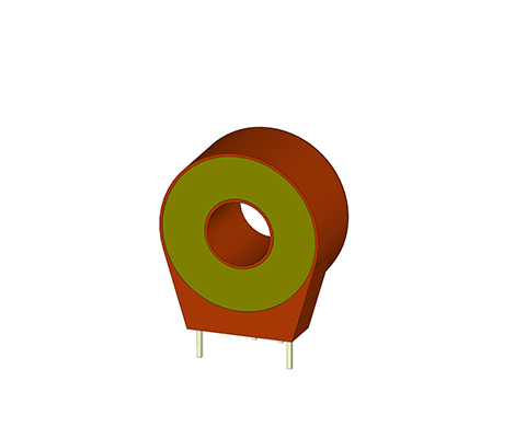
Current transformers for PCB mounting Description REO current transformers of the IB series are particularly well suited for mounting on printed circuit boards in the electronics sector of modern drive technology for control purposes and measured value acquisition. Advantages small space requirement PCB mounting according to UL 94 V0 Accuracy class 1 Measurement in the frequency range 50-400Hz low phase error for power measurement very low magnetic reversal and eddy current losses Electrically isolated primary and secondary circuits easy-to-install designs Technical data Type IB 0,5/5 IB 0,5/20 IB 0,5/40 Primary current [A] IPN 0 – 5 0 – 20 0 – 40 Max. Primary current [A] ImaxPN 7 25 50 Secondary current [mA] IaN 0 – 10 0 – 25 0 – 40 Power [VA] Psek 0 – 0,010 0 – 0,025 0 – 0,040 Translation ratio KN 1:500 1:800 1:1000 Burden resistance [Ω] RB 100 40 25 Burden voltage [V] URB 0 – 1 Measuring accuracy 50 Hz [%] FU ≤ 1 Ambient temperature [°C] TA 0..+85 Frequency range [Hz] f 50 – 400 Insulation test voltage [kVac] VP 3 Dimensions in MM Type Primary current [A] Height [mm] Width [mm] Depth [mm] Opening [mm] PIN thickness [mm] PIN length [mm] IB 05/5 0 – 5 30 26,5/17,5 14,5 10,5 0,7×0,7 5,0 IB 05/20 0 – 20 30 26,5/17,5 14,5 10,5 0,7×0,7 5,0 IB 05/40 0 – 40 30 26,5/17,5 14,5 10,5 0,7×0,7 5,0 Datasheet All data and configurations can be found in our product datasheet. Download Datasheet Certifications