
PASSIVE CURRENT TRANSFORMER Series IN (Stranded Wire / Terminal)

Current transformer (stranded wire/terminal) Description The increasing development and distribution of electronic devices with higher working frequencies requires current transformers with an extended frequency range. This requirement can be met with specially selected materials in conjunction with an optimized design. Advantages Stranded wires or terminals according to UL 94 V-0 Current transformer for more accurate current measurement higher accuracy classes 1; 0.5; 0.2 than with standard-IE Measurement in the frequency range 16 2/3 to 50kHz Pulse measurement (e.g. 8/20μs) low phase error for power measurement very low remagnetization losses and eddy current losses Nanocrystalline toroidal cores with a strip thickness of e.g. 20μm Electrically isolated primary and secondary circuits easy-to-install designs Versatile housing options with different through-hole openings Technical data According to: EN/IEC 61869-1/2 Rated primary current: 50 – 1000 A Frequency range: 50 – 50,000 Hz Type 50 100 300 500 1000 Primary current [A] IPN 50 100 300 500 1000 Max. Primary current [A] ImaxPN 60 120 360 600 1200 Secondary current [mA] IaN 1000 1000 1000 1000 1000 Power [VA] Psek 0,5 1,0 2,5 5,0 15 Transformation ratio KN 50 100 300 500 1000 Burden resistance [Ω] RB 0,5 1,0 2,5 5,0 15 Burden voltage [V] URB 0,5 1,0 2,5 5,0 15 Measuring accuracy 50 Hz [%] FU 1,0 1,0 1,0 1,0 1,0 Ambient temperature [°C] TA -25 to +70 -25 to +70 -25 to +70 -25 to +70 -25 to +70 Frequency range [Hz] f 0.05 to 50 0.05 to 50 0.05 to 50 0.05 to 50 0.05 to 50 Insulation test voltage [kVac] VP 3 3 3 3 3 Dimensions in MM Type Connection[mm²] h[mm] b1/b2[mm] t[mm] DL[mm] p/s[mm] a[mm] c1/c2[mm] f[mm] e[mm] l[mm] IE/50 2,5 70 70/89 33 31 57/57 77 15,5/… 4,3 6×4,3 25 IE/100 2,5 70 70/89 33 31 57/57 77 15,5/… 4,3 6×4,3 25 IE/300 2,5 95 94/110 44 40 78/78 100 18/… 5,3 8×5,3 25 IE/500 2,5 95 94/110 44 40 78/78 100 18/… 5,3 8×5,3 25 IE/1000 2,5 141 138/170 55 64 120/120 150 18/25 6,5 10×6,5 25 Datasheet All data and configurations can be found in our product datasheet. Download Datasheet
PASSIVE CURRENT TRANSFORMER SERIES IE MODULAR
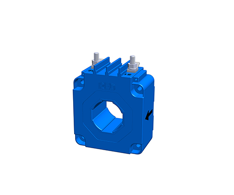
Through-hole current transformer (module base) Description With through-hole current transformers, the primary conductor provided by the customer is inserted through the current transformer opening in the housing. The through-hole opening is oriented to the primary current strength. Wound current transformers have a primary winding and a secondary winding. Both windings are applied to the closed ring core and separated from each other by insulation. This principle is predominantly used for small primary currents. Advantages Bolt or flat plug connection Through-hole current transformer for direct conductor routing Toroidal cores made of high-quality magnetic cores Frequency range 16 2/3 to 400 Hz optional High core output power and high-quality insulation Electrically isolated primary and secondary circuits Easy-to-install module housings Variable connections, e.g., bolts, plugs, flat plugs, strands Versatile housing options with different through-hole openings Typical Applications Industry, Renewable Energies, Railway Technology, Energy, Automation and Building Technology Technical data Type IE modular 500 1000 2500 IPN Rated primary current 500 1000 2500 [A] ImaxPN Max. rated primary current 600 1200 3000 [A] IaN Secondary current 1000 [mA] RB Burden resistance 5 15 30 [Ω] URB Burden voltage 5 15 30 [V] PSek Power 5 15 30 [VA] KN Transformation ratio 500 1000 2500 Fi Measurement accuracy (50 Hz) 0,5 0,5 0,5 [%] f Frequency 50-400 [Hz] TA Ambient temperature -25 to +70 [°C] Vp Insulation test 3 [KVac] Connection MS-bolt / flat plug 6.3 x 0.8 [mm²] Weight 0.8 0.8 1.8 [kg] Standards 61869-2 Dimensions in MM Type I [mm] h1/h2 [mm] t1/t2 [mm] s1/s2 [mm] b1/b2 [mm] D [mm] D1xD2 [mm] f [mm] e [mm] x1/x2 [mm] IE modular 500 70 76/35 38/64 57/57 57/50 30,2 30.4×10.4 4,3 4,3 36/15 IE modular 1000 94 100/47 42/72 78/78 78/60 38,5 40.5×13.5 5,3 5,3 36/15 IE modular 2500 135 141/67,5 52/88 102/102 102/70 57,5 60.5×20.5 6,5 6,5 36/15 Datasheet All data and configurations can be found in our product datasheet. Download Datasheet
PASSIVE CURRENT TRANSFORMER SERIES IE (Stranded Wire / Terminal)
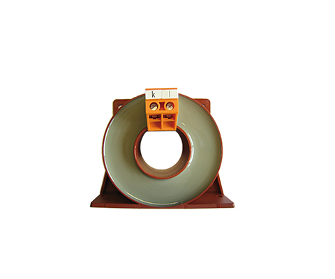
Feed-through current transformer (stranded wire/terminal) Description With feed-through current transformers, the primary conductor on the construction side is pushed through the current transformer opening in the housing. The feed-through opening is oriented towards the primary current strength. Wound current transformers have a primary winding and a secondary winding. Both windings are applied to the closed toroidal core and separated from each other by insulation. This principle is mainly used for small primary currents. Advantages Stranded wires or terminals according to UL 94 V0 Clip-on current transformer for direct conductor routing Design as wound transformer for small currents Ring band cores made of high-quality silicon iron Measurement in the lower frequency range 16 2/3 to 400Hz High core output power and high-quality insulation Electrically isolated primary and secondary circuits easy-to-install designs Versatile housing options with different through-hole openings Advantages (mechanical) easy-to-install designs Variable connections e.g. terminals, plugs, flat plugs, stranded wires or PCB mounting versatile housing range with different Feed-through openings very long service life Typical Applications Industry, Renewable Energies, Railway Technology, Energy, Automation and Building Technology Technical data Type 50 100 300 500 1000 2000 3000 Primary current [A] IPN 50 100 300 500 1000 2000 3000 Max. Primary current [A] ImaxPN 60 120 360 600 1200 2400 3600 Secondary current [mA] IaN 1000 1000 1000 1000 1000 1000 1000 Power [VA] Psek 0,5 1,0 2,5 10 15 25 25 Transformation ratio KN 50 100 300 500 1000 2000 3000 Burden resistance [Ω] RB 0,5 1,0 2,5 10 15 25 25 Burden voltage [V] URB 0,5 1,0 2,5 10 15 25 25 Measuring accuracy 50 Hz [%] FU 1,0 1,0 1,0 1,0 1,0 1,0 1,0 Ambient temperature [°C] TA -25 to + 70 -25 to + 70 -25 to + 70 -25 to + 70 -25 to + 70 -25 to + 70 -25 to + 70 Frequency range [Hz] f 50 to 400 50 to 400 50 to 400 50 to 400 50 to 400 50 to 400 50 to 400 Insulation test voltage [kVac] VP 3 3 3 3 3 3 3 Datasheet All data and configurations can be found in our product datasheet. Download Datasheet Certifications