
EMI-Filter CNW 102
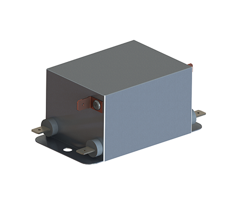
Single-phase line filter (2 conductors, two-stage) DESCRIPTION Recommended filter for interference suppression according to EN 55011, Class B and EN 61800-3, Category C1. Cost-effective filter that is well-suited for direct mounting in the housing of an interference source due to its small dimensions and very good attenuation values in a two-stage design. The filter is also available as a version with low leakage current as well as a special medical version (without Y-capacitors). Optionally, the filter can also be supplied with overvoltage protection. A quick installation can be performed using connection with insulated flat connectors. However, versions with other connection options (terminal / wire) are also possible. ADVANTAGES Small dimensions quick connection touch-proof if used with insulated spade connectors very good damping performance at a low leakage current also as a medical version or with a lower leakage current available optional anti-surge protection UL approval for the complete model range – E217177 (not for N- and MED-versions) TYPICAL APPLICATIONS Applications: Switch-mode power supplies for industrial electronics, frequency converters for motor drives, power supply units, medical and telecommunication applications, DC applications TECHNICAL SPECIFICATION Conforming to: VDE 0565-3 / IEC 950 / UL 1283 Test voltage: L-N 2100 V, DC 1s, L/N-PE 2700 V, DC 1s Overload: 1,5 x I 1 min/h Climatic category: DIN IEC 68 Part 1 25/085/21 Type Rated voltage [V] Rated current [A] Leakage current [A][mA] Cx [μF] Cy nF] L [mH] R [kOhm] CNW 102/3 250 3 <3,5 0,94 20 13,6 560 CNW 102/6 250 6 <3,5 0,94 20 7,8 560 CNW 102/10 250 10 <3,5 0,94 20 3,6 560 CNW 102/16 250 16 <3,5 0,94 20 2,4 560 CNW 102/20 250 20 <3,5 0,94 20 2,0 560 CNW 102/3/N 250 3 <0,5 0,94 4,4 13,6 560 CNW 102/6/N 250 6 <0,5 0,94 4,4 7,8 560 CNW 102/10/N 250 10 <0,5 0,94 4,4 3,6 560 CNW 1022/16/N 250 16 <0,5 0,94 4,4 2,4 560 CNW 102/20/N 250 20 <0,5 0,94 4,4 2,0 560 CNW 102/3/MED 250 3 <0,005 0,94 – 13,6 560 CNW 102/6/MED 250 6 <0,005 0,94 – 7,8 560 CNW 102/10/MED 250 10 <0,005 0,94 – 3,6 560 CNW 102/16/MED 250 16 <0,005 0,94 – 2,4 560 CNW 102/20/MED 250 20 <0,005 0,94 – 2,0 560 DIMENSIONS IN MM Type Connection /PE-Connection B [mm] D [mm] H [mm] L1 [mm] L2[mm] L3[kOhm] CNW 102/3 Flat plug 6,3×0,8 50 5,3 40 87 75 65 CNW 102/6 Flat plug 6,3×0,8 50 5,3 40 87 75 65 CNW 102/10 Flat plug 6,3×0,8 50 5,3 40 87 75 65 CNW 102/16 Flat plug 6,3×0,8 53 5,3 40 110 100 90 CNW 102/20 Flat plug 6,3×0,8 53 5,3 40 110 100 90 Data sheet Download our extensive catalog and discover many other REO products. Download Datenblatt Certifications
EMI-Filter CNW 101
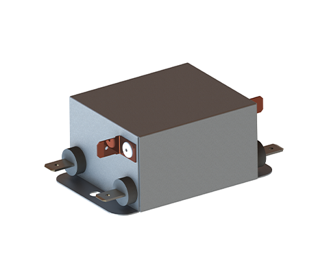
Single-phase line filters (2 lines, single-stage) DESCRIPTION Recommended filter for interference suppression according to EN 55011, Class A and EN 61800-3, Category C2. Cost-effective filter that, due to its small dimensions and good attenuation values with a single-stage design, is well-suited for direct mounting in the housing of an interference source. The filter is also available as a version with low leakage current as well as a special medical version (without Y-capacitors). Optionally, the filter can also be supplied with overvoltage protection. The connection with insulated flat connectors allows for quick and touch-safe installation. However, versions with other connection options (terminal / stranded wire) are also possible. ADVANTAGES Small dimensions quick connection touch-proof if used with insulated spade connectors good damping performance at a low leakage current also available as a medical version or with a lower leakage current optional anti-surge protection UL approval for the complete model range – E217177 (not for N- and MED-versions) TYPICAL APPLICATIONS Switch-mode power supplies for industrial electronics, telecommunications, data systems engineering and DC applications. TECHNICAL SPECIFICATION Conforming to: VDE 0565-3 / IEC 950 / UL 1283 Test voltage: L-N 2100 V, DC 1s, L/N-PE 2700 V, DC 1s Overload: 1,5 x I 1 min/h Climatic category: DIN IEC 68 Part 1 25/085/21 Type Nominal voltage [V] Nominal current [A] Leakage current [mA] Cx [μF] Cy nF] L [mH] R [kOhm] CNW 101/3 250 3 <3,5 0,94 20 3,3 560 CNW 101/6 250 6 <3,5 0,94 20 1,8 560 CNW 101/10 250 10 <3,5 0,94 20 1,8 560 CNW 101/16 250 16 <3,5 0,94 20 1,2 560 CNW 101/20 250 20 <3,5 0,94 20 1,0 560 CNW 101/3/N 250 3 <0,5 0,94 20 3,3 560 CNW 101/6/N 250 6 <0,5 0,94 20 1,8 560 CNW 101/10/N 250 10 <0,5 0,94 20 1,8 560 CNW 101/16/N 250 16 <0,5 0,94 20 1,2 560 CNW 101/20/N 250 20 <0,5 0,94 20 1,0 560 CNW 101/3/MED 250 3 <0,005 0,94 – 3,3 560 CNW 101/6/MED 250 6 <0,005 0,94 – 1,8 560 CNW 101/10/MED 250 10 <0,005 0,94 – 1,8 560 CNW 101/16/MED 250 16 <0,005 0,94 – 1,2 560 CNW 101/20/MED 250 20 <0,005 0,94 – 1,0 560 DIMENSIONS IN MM Type Connection /PE-Connection B [mm] D [mm] H [mm] L1 [mm] L2 [mm] L3 [kOhm] CNW 101/3 Flat plug 6,3×0,8 45 4,2 30 70 60 52 CNW 101/6 Flat plug 6,3×0,8 45 4,2 30 70 60 52 CNW 101/10 Flat plug 6,3×0,8 50 5,3 30 85 75 65 CNW 101/16 Flat plug 6,3×0,8 50 5,3 30 85 75 65 CNW 101/20 Flat plug 6,3×0,8 50 5,3 30 85 75 65 Data sheet Download our extensive catalog and discover many other REO products. Download Datenblatt Certifications
REOTRON MDZ 2000

Ignition and Control Device DESCRIPTION The control devices of the REOTRON MDZ2000 series are microprocessor-controlled devices for controlling power thyristors in 6-pulse rectifier systems. The devices include the control and regulation electronics as well as the ignition pulse generation and the ignition pulse output stages. The rectifier can be operated as a current regulator or voltage regulator, with an automatic switchover to the smaller setpoint. The required setpoints can be specified by external potentiometers, control signals 0…10 V, DC or 0…20 mA / 4…20 mA DC or via the integrated control display. The actual value inputs are standardly designed for +/- 0…40 V rectifier output voltage and +/- 0…75 mV output current, but 0…10 V, DC normalized input signals are also possible. Function The REOTRON MDZ control and ignition devices are designed for controlling rectifier systems. They contain one controller each for current and voltage regulation. In voltage regulation mode, the output voltage specified by the setpoint is kept constant by an internal control loop, so load changes or mains voltage fluctuations have no influence on the output voltage. If the device is operated as a current regulator, the output current of the device is compared with the setpoint and the device output is regulated accordingly. The output voltage can rise up to the maximum value. Reaching the limit values Imax and control limit is indicated by LEDs. If both setpoints are used during operation, the controller with the smaller setpoint always has priority. This means that, for example, in voltage regulation with underlying current regulation, the voltage regulator is active as long as the permitted current value is not exceeded. If the current limit is reached, the current regulator has priority. If the device is to operate as a pure voltage or current regulator, the other setpoint input must be bridged to the reference voltage (10 V, DC). ADVANTAGES Use as three-phase thyristor controller or fully controlled three-phase bridge Connection to clockwise or counterclockwise rotating field possible (self-detecting) Current or voltage regulation Selection option for transformer vector group Switchable to controller operation without control functions External setpoint specification Input for overtemperature switch Fault indication Usable as three-phase thyristor controller with downstream transformer and passive bridge rectifier TECHNICAL SPECIFICATION Device type REOTRON MDZ 2000 Mains connection 3x 400 V +6%-10% 50/60 Hz Ignition pulse stages 6 Pulse voltage approx. 12 V Pulse current 500 mA Transformer vector groups Dd0, Yy0, Dz0, Dy5, Yd5, Yz5,Dd6, Yy6, Dz6, Dy11,Yd11, Yz11 and Primary controller Voltage setpoint 0…10 V, DC / 0…20 mA / 4…20 mA / Pot 10 kΩ Current setpoint 0…10 V, DC / 0…20 mA / 4…20 mA / Pot 10 kΩ Actual value input voltage +/- 0…40 V (0…10 V, DC option) Actual value input current +/- 0…100 mV (0…10 V, DC option) Ramp-up/down integrator 0.1…10 seconds adjustable Voltage controller PI controller P-component adjustable Current controller PI controller P-component adjustable Input impedance actual value input voltage 56 kΩ Input impedance actual value input current 5.6 Ω Control signal pulse enable 12…24 V, DC / 2.5 mA Control signal setpoint lock 12…24 V, DC / 2.5 mA Overtemperature input Switch 1 mA Fault relay 1 changeover contact load 250 V, 1 A Status relay 1 changeover contact load 250 V, 1 A Permissible Ambient temperature 0…45 °C Dimensions (WxHxD) 140x290x160 mm
Three-phase Thyristor Controller Reotron MDW 700

3-phase thyristor power controller DESCRIPTION REOTRON MDW thyristor controllers are used in industrial process engineering, especially in applications where accurate regulation of the load is required.The MDW range can operate as phase-angle or in burst-fire mode as standard and is able to function as voltage, current or power regulators ensuring maximum versatility.REOTRON MDW controllers can be directly connected to the load (Infrared heating) or can also be used for primary control of transformers for load isolation and allow more favourable combinations for operation of voltage/current (resistance heating applications)The REOTRON MDW is a modern microprocessor controlled device with integrated monitoring of voltage and current to ensure that accurate regulation occurs.Communication with the devices can be done using conventional analog interfaces (0…10V,DC or 0(4)…20 mA), potentiometer or field bus systems like DeviceNet, ProfiBus, CanBus, EtherCAT, EtherNet/IP and ProfiNet to allow easy integration into new or existing factory control networks.To provide additional functionality the units also provide 0..+10V,DC analog outputs which are proportional to current and voltage. These can easily be interfaced to external measurement and supervisory systems.The units have a wide variety of user adjustable parameters so that control can be tailored and optimized for the application, for example Current/Voltage Limit and ramp-up and ramp-down times. The REOTRON MDW range is protected to IP20 and is designed to be integrated into control cabinets.They are air-cooled and above 150A have integral cooling fans. In addition to this, the REOTRON MDW-WK are designed for water-cooling and can easily be integrated into new or existing cooling systems. Advantages phase-angle or burst-fire controllers measuring of effective values connection via analog interfaces, potentiometers or field bus systems Air or water- cooling installation device for control cabinets Technical specifications REOTRON MDW 700-10 3 x 400 V AC, +/- 10% 3 x 0…400 V 3 x 10 A REOTRON MDW 700-25 3 x 400 V AC, +/- 10% 3 x 0…400 V 3 x 25 A REOTRON MDW 700-50 3 x 400 V AC, +/- 10% 3 x 0…400 V 3 x 50 A REOTRON MDW 700-80 3 x 400 V AC, +/- 10% 3 x 0…400 V 3 x 80 A REOTRON MDW 700-110 3 x 400 V AC, +/- 10% 3 x 0…400 V 3 x 110 A REOTRON MDW 700-150 3 x 400 V AC, +/- 10% 3 x 0…400 V 3 x 150 A REOTRON MDW 700-200 3 x 400 V AC, +/- 10% 3 x 0…400 V 3 x 200 A REOTRON MDW 700-300 3 x 400 V AC, +/- 10% 3 x 0…400 V 3 x 300 A REOTRON MDW 700-115* 3 x 400 V AC, +/- 10% 3 x 0…400 V 3 x 115 A REOTRON MDW 700-160* 3 x 400 V AC, +/- 10% 3 x 0…400 V 3 x 160 A REOTRON MDW 700-250* 3 x 400 V AC, +/- 10% 3 x 0…400 V 3 x 250 A REOTRON MDW 700-350* 3 x 400 V AC, +/- 10% 3 x 0…400 V 3 x 350 A REOTRON MDW 700-450* 3 x 400 V AC, +/- 10% 3 x 0…400 V 3 x 450 A Load Type Resisive/ Induktive Target Value: Storm, Voltage, Power 0…+10 V, DC 0(4)…20 mA Internal keyboard Interface (optional) Profibus-DP, CAN-Bus, DeviceNet, EtherCAT Release Input 24 V, DC, external contact (potential-free) Status update ready , status update power on Relay, changeover contact Relay, changeover contact Display for effective value : Current/Voltage 0…+10 V, DC Betriebstemperatur 0…+45°C Storage/ Transport temperature -10…+70°C Protection rating IP 20 * with water cooling
Single-phase Thyristor Controller Reotron MEW 700

Single-Phase Thyristor Controller DESCRIPTION REOTRON MEW series, single-phase, microprocessor-based, thyristor-controllers are suitable for resistive or resistive/inductive loads, especially those with a high Rcold / Rwarm coefficient. Status relays indicate unit ready and fault conditions. Depending on the settings, the controller normally operates on the phase-angle principle (standard setting). It can also be used in a burst-fire mode. Phase-angle mode the unit works as a regulator for RMS current, RMS voltage or power. Adjustment is variable.External setpoint signals can be used for controlling current, voltage and power or potentiometers may be used instead. A serial RS232, PROFIBUS-DP field bus interface can be used for remote adjustment. All unit settings can be made through the controller’s front panel, using a LED display and keypad In the proportional regulation. Advantages Operation via LED display and buttons switchable between phase-angle or full-wave cycle operation Integrated semiconductor fuses Current, voltage or power control Interfaces: DeviceNet, ProfiBus, CanBus, EtherCAT, EtherNet / IP and ProfiNet (optional) Actual value feedback: current, voltage or power Technical data* REOTRON MEW 700-10 230 v AC, +/- 10%, 400 V AC, +/- 10% 0…230 V 0…400 V 10 A REOTRON MEW 700-25 230 v AC, +/- 10%, 400 V AC, +/- 10% 0…230 V 0…400 25 A REOTRON MEW 700-50 230 v AC, +/- 10%, 400 V AC, +/- 10% 0…230 V 0…400 50 A REOTRON MEW 700-80 230 v AC, +/- 10%, 400 V AC, +/- 10% 0…230 V 0…400 80 A REOTRON MEW 700-110 230 v AC, +/- 10%, 400 V AC, +/- 10% 0…230 V 0…400 110 A REOTRON MEW 700-150 230 v AC, +/- 10%, 400 V AC, +/- 10% 0…230 V 0…400 150 A REOTRON MEW 700-200 230 v AC, +/- 10%, 400 V AC, +/- 10% 0…230 V 0…400 200 A REOTRON MEW 700-300 230 v AC, +/- 10%, 400 V AC, +/- 10% 0…230 V 0…400 300 A Load Type Resisive/ Induktive Target Value: Storm, Voltage, Power 0…+10 V, DC 0(4)…20 mA Internal keyboard Interface: (Optional) Profibus-DP, CAN-Bus, DeviceNet, ErtherCAT, ErtherNet/IP, ProfiNet Release Input 24 V, DC, external contact (potential-free) Status message ready for operation, Status message power on Relay changeover contact, Relay changeover contact Actual value monitor: Current/voltage 0…+5 V, DC Betriebstemperatur 0…+45°C Storage/ Transport temperature -10…+70°C Protection rating IP 20 *Higher services on reguest
1-PHASE THYRISTOR-CONTROLLER REOTRON EW 514

1-PHASE THYRISTOR-CONTROLLER Description The REOTRON EW 514 is a single-phase thyristor power regulator for load currents up to 6 A.The control electronics are isolated from the mains voltage. The REOVIB 509 is designed for controlling bowl or linear feeders up to 15 A current rating. The output frequency 50Hz/100Hz (60Hz/120Hz) is selected to suit the feeder. In the regulation circuit there is built-in compensation for mains variations. The setpoint can be set via a potentiometer, a control voltage 0…+ 10 V, DC or via a control current 0(4)…20 mA. The adjustment of the usable setpoint range can be achieved by the internal trimming potentiometers Umin/Umax. Furthermore, an enable input is provided for start/stop operation and there is a control input for use with a track control module (REOVIB 513). Mains fluctuations are compensated by an internal control stage. Fixings are provided for DIN rail mounting according to EN 50022-35. Advantages Mains voltage compensation Setpoint via potentiometer0…+10 V, 0(4)…20 mA Enable input 24 V, DC or contact Snap-on mounting for 35 mm DIN rail Technical specifications Input voltage : 230 V + 6% / – 10% Output voltage : 0…230 V Output Current : 6 A Input voltage switchable : Input voltage switchable [V] Technical specifications Input voltage 230V, +6% / – 10%, 50/60 Hz Output voltage 0…230 V Output current 6 A Sollwert external with 0…+ 10 V, DC 0(4)…20mA, Potentiometer 10 kOhm Release 24 V, DC or contact Operating temperature 0…+45° C Protection IP20 Dimensions in mm Type A[mm] B[mm] C[mm] REOTRON EW 509 102 77 114
1-phase thyristor controler REOTRON EW 509

Thyristor power regulator Description REOTRON EW 509 is a single-phase thyristor control for currents up to 15 A. The control electronics is free of mains potential. The REOVIB 509 is designed for controlling bowl or linear feeders up to 15 A current rating. The output frequency 50Hz/100Hz (60Hz/120Hz) is selected to suit the feeder. In the regulation circuit there is built-in compensation for mains variations. The feed rate setpoint can be derived from a potentiometer, a voltage signal 0…+10 VDC or a current signal 0…20 mA. The setpoint range can be linearised by means of two trimmers Umin/Umax. Furthermore, an enable input is provided for start/stop operation and there is a control input for use with a track control module (REOVIB 513). Mains fluctuations are compensated by an internal control stage. Fixings are provided for DIN rail mounting according to EN 50022-35. Advantages Mains voltage compensation Setpoint via potentiometer 0…+10 V, 0(4)…20 mA Enable input 24 V, DC or contact Snap-on mounting for 35 mm DIN rail Technical specifications Input voltage : 230 / 400 V + 6% / – 10% Output voltage : 0…Ue V Output Current : 15 A Input voltage switchable Input voltage switchable [V] V Input voltage 230V, +6% / – 10%, 50/60 Hz, 400V, +6% / – 10%, 50/60 Hz Output voltage 0…230 V, 0…400 V Output current 15 A Setpoint external with 0…+ 10 V, DC 0(4)…20mA, Potentiometer 10 kOhm Release 24 V, DC or contact Operating temperature 0…+45° C Protection IP20 Dimensions in mm Type A[mm] B[mm] C[mm] D[mm] REOTRON EW 509 150 74 112 100
DC-Power supply REOTRON SMP-LM
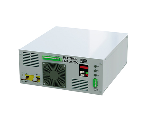
Benchtop DESCRIPTION The DC power supplies from the REOTRON SMP series are primary switched switching power supplies with galvanic isolation from the input to the output. The devices can be used as voltage, current or power regulators. Operation The unit can be operated from an internal display, external control signals of 0…+10V, 0(4)…20mA or optionally by a fieldbus interface such as DeviceNet, ProfiBus, CanBus, EtherCAT, EtherNet/IP and ProfiNet protocols. Input devices The device input is designed for connection to a three-phase mains 3 x 400 V, 50/60 Hz. The compliance of EMC standards is guaranteed by an input-sided PFC-mains filter. Design The devices have a compact design in a 19 inch rackmount chassis and can be delivered as a installation ready control cabinet version or as a tabletop unit (lab version). The devices are air- or water-cooled. Connection The SMP‘s are connected via screw terminals and with cooper terminal buses at high output currents. Like all REO-products, the REOTRON SMP‘s are also available as customized versions. ADVANTAGES Very good cos Φ of 0,95 Compact dimensions Series or parallel connection Air or water- cooling Many options of combinations for different requirements with otherREO product ranges TECHNICAL SPECIFICATION Type REOTRON SMP-ESM plug-in module Input voltage 3 x 400 V, +/- 10%, 50/60 Hz Ripple P-P 100 mV/ 200 mV Setpoint Input 0…+10 V, DC, 0(4)…20mA, Potentiometer 10 kOhm internally via the control display Actual Value Output 0…+10 V, DC, 0(4)…20mA, internally via the control display Interfaces (Option) ProfiBus-DP, DeviceNet, CAN-Bus, ProfiNet, EtherNet/IP, EtherCAT Control Accuracy 1% of the nominal value (higher on reguest) Release 24 V, DC or contact Protection Class Control cabinet installation IP 20 2 x Status Relays Changeover 250 V, 1A Efficiency > 85% Cos Φ 0,95 Operating Temperature 0… 40° C Standards EN 50178, EN 61000-6-2, EN 61000-6-4 REO series SMP-LM 25-40 SMP-LM 25-100 SMP-LM 25-200 SMP-LM 25-300 SMP-LM 25-400 SMP-LM 25-500 SMP-LM 25-600 Output power [W] 0…1000 0…2500 0…5000 0…7500 0…10000 0…12500 0…15000 Output voltage [V] 0…25 0…25 0…25 0…25 0…25 0…25 0…25 Output current [A] 0…40 0…100 0…200 0…300 0…400 0…500 0…600 Dimensions (WxDxH) [BxTxHE] 482×406/4HE 434×465/4HE 434×465/4HE 434×465/4HE 434×465/6HE 434×465/6HE 434×465/6HE Output power [W]0…10000…25000…50000…75000…100000…125000…15000 REO series SMP-LM 50-20 SMP-LM 50-50 SMP-LM 50-100 SMP-LM 50-150 SMP-LM 50-200 SMP-LM 50-250 SMP-LM 50-300 Output voltage [V] 0…50 0…50 0…50 0…50 0…50 0…50 0…50 Output current [A] 0…20 0…50 0…100 0…150 0…200 0…250 0…300 Dimensions (WxDxH) [BxTxHE] 434×465/4HE 434×465/4HE 434×465/4HE 434×465/4HE 434×465/6HE 434×465/6HE 434×465/6HE REO series SMP-LM 80-13 SMP-LM 80-31 SMP-LM 80-63 SMP-LM 80-94 SMP-LM 80-125 SMP-LM 80-156 SMP-LM 80-188 Output power [W] 0…1000 0…2500 0…5000 0…7500 0…10000 0…12500 0…15000 Output voltage [V] 0…80 0…80 0…80 0…80 0…80 0…80 0…80 Output current [A] 0…13 0…31 0…63 0…94 0…125 0…156 0…188 Dimensions (WxDxH) [BxTxHE] 434×465/4HE 434×465/4HE 434×465/4HE 434×465/4HE 434×465/6HE 434×465/6HE 434×465/6HE REO series SMP-LM 150-7 SMP-LM 150-17 SMP-LM 150-33 SMP-LM 150-50 SMP-LM 150-67 SMP-LM 150-83 SMP-LM 150-100 Output power [W] 0…1000 0…2500 0…5000 0…7500 0…10000 0…12500 0…15000 Output voltage [V] 0…80 0…80 0…80 0…80 0…80 0…80 0…80 Output current [A] 0…13 0…31 0…63 0…94 0…125 0…156 0…188 Dimensions (WxDxH) [BxTxHE] 434×465/4HE 434×465/4HE 434×465/4HE 434×465/4HE 434×465/6HE 434×465/6HE 434×465/6HE REO series SMP-LM 250-40 SMP-LM 250-10 SMP-LM 250-20 SMP-LM 250-30 SMP-LM 250-40 SMP-LM 250-50 SMP-LM 250-60 Output power [W] 0…1000 0…2500 0…5000 0…7500 0…10000 0…12500 0…15000 Output voltage [V] 0…250 0…250 0…250 0…250 0…250 0…250 0…250 Output current [A] 0…4 0…10 0…20 0…30 0…40 0…50 0…60 Dimensions (WxDxH) [BxTxHE] 434×465/4HE 434×465/4HE 434×465/4HE 434×465/4HE 434×465/6HE 434×465/6HE 434×465/6HE REO series SMP-LM 400-2,5 SMP-LM 400-6,25 SMP-LM 400-12,5 SMP-LM 400-18,75 SMP-LM 400-25 SMP-LM 400-31,25 SMP-LM 400-37,5 Output power [W] 0…1000 0…2800 0…5200 0…7600 0…10000 0…12800 0…15000 Output voltage [V] 0…400 0…400 0…400 0…400 0…400 0…400 0…400 Output current [A] 0…2,5 0…6,25 0…13 0…19 0…25 0…32 0…37,5 Dimensions (WxDxH) [BxTxHE] 434×465/4HE 434×465/4HE 434×465/4HE 434×465/4HE 434×465/6HE 434×465/6HE 434×465/6HE REO series SMP-LM 600-2 SMP-LM 600-4 SMP-LM 600-8 SMP-LM 600-13 SMP-LM 600-17 SMP-LM 600-21 SMP-LM 600-25 Output power [W] 0…1200 0…2400 0…4800 0…7800 0…10200 0…12600 0…15000 Output voltage [V] 0…600 0…600 0…600 0…600 0…600 0…600 0…600 Output current [A] 0…2 0…4 0…8 0…13 0…17 0…21 0…25 Dimensions (WxDxH) [BxTxHE] 434×465/4HE 434×465/4HE 434×465/4HE 434×465/4HE 434×465/4HE 434×465/4HE 434×465/4HE
DC-Power supply REOTRON SMP-SMB
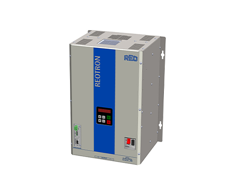
Installation – Mounted on mounting wall DESCRIPTION The DC power supplies from the REOTRON SMP series are primary switched switching power supplies with galvanic isolation from the input to the output. The devices can be used as voltage, current or power regulators. Operation The unit can be operated from an internal display, external control signals of 0…+10V, 0(4)…20mA or optionally by a fieldbus interface such as DeviceNet, ProfiBus, CanBus, EtherCAT, EtherNet/IP and ProfiNet protocols. Input devices The device input is designed for connection to a three-phase mains 3 x 400 V, 50/60 Hz. The compliance of EMC standards is guaranteed by an input-sided PFC-mains filter. Design The devices have a compact design in a 19 inch rackmount chassis and can be delivered as a installation ready control cabinet version or as a tabletop unit (lab version). The devices are air- or water-cooled. Connection The SMP‘s are connected via screw terminals and with cooper terminal buses at high output currents. Like all REO-products, the REOTRON SMP‘s are also available as customized versions. ADVANTAGES Very good cos Φ of 0,95 Compact dimensions Series or parallel connection Air or water- cooling Many options of combinations for different requirements with otherREO product ranges TECHNICAL SPECIFICATION Type REOTRON SMP-SMB control cabinet module Input voltage 3x400V, +/- 10%, 50/60 Hz Ripple P-P 100 mV/ 200 mV Setpoint Input 0…+10 V, DC, 0(4)…20mA, Potentiometer 10 kOhm internally via the control display Actual value output 0…+10 V, DC, 0(4)…20mA, internally via operating display Interfaces (Option) ProfiBus-DP, DeviceNet, CAN-Bus, ProfiNet, EtherNet/IP, EtherCAT Control Accuracy 1% of the nominal value (higher on reguest) Release 24 V, DC or contact Protection Class Control cabinet installation IP 20 2 x Status Relays Changeover 250 V, 1A Efficiency > 85% Cos Φ 0,95 Operating Temperature 0… 40° C Standards EN 50178, EN 61000-6-2, EN 61000-6-4 Size Width Height Depth Small(S) 300 400 230 Medium (M) 330 450 250 Large (L) 400 480 300 Extra large (XL) 600 600 300 REO series Small(S) SMP-SMB 25-40 Small(S) SMP-SMB 25-100 Medium(M) SMP-SMB 25-200 Medium(M) SMP-SMB 25-300 Large (L) SMP-SMB 25-400 Large (L) SMP-SMB 25-500 Large (L) SMP-SMB 25-600 Output power [W] 0…1000 0…2500 0…5000 0…7500 0…10000 0…12500 0…15000 Output voltage [V] 0…25 0…25 0…25 0…25 0…25 0…25 0…25 Output current [A] 0…40 0…100 0…200 0…300 0…400 0…500 0…600 REO series Small(S) SMP-SMB 50-20 Small(S) SMP-SMB 50-50 Medium(M) SMP-SMB 50-100 Medium(M) SMP-SMB 50-150 Large(L) SMP-SMB 50-200 Large(L) SMP-SMB 50-250 Large(L) SMP-SMB 50-300 Output power [W] 0…1000 0…2500 0…5000 0…7500 0…10000 0…12500 0…15000 Output voltage [V] 0…50 0…50 0…50 0…50 0…50 0…50 0…50 Output current [A] 0…20 0…50 0…100 0…150 0…200 0…250 0…300 REO series Small(S) SMP-SMB 80-13 Small(S) SMP-SMB 80-31 Medium(M) SMP-SMB 80-63 Medium(M SMP-SMB 80-94 Large(L) SMP-SMB 80-125 Large(L) SMP-SMB 80-156 Large(L) SMP-SMB 80-188 Output power [W] 0…1000 0…2500 0…5000 0…7500 0…10000 0…12500 0…15000 Output voltage [V] 0…80 0…80 0…80 0…80 0…80 0…80 0…80 Output current [A] 0…13 0…31 0…63 0…94 0…125 0…156 0…188 REO series Small(S) SMP-SMB 150-7 Small(S) SMP-SMB 150-17 Medium(M) SMP-SMB 150-33 Medium(M) SMP-SMB 150-50 Large(L) SMP-SMB 150-67 Large(L) SMP-SMB 150-83 Large(L) SMP-SMB 150-100 Output power [W] 0…1000 0…2500 0…5000 0…7500 0…10000 0…12500 0…15000 Output voltage [V] 0…150 0…150 0…150 0…150 0…150 0…150 0…150 Output current [A] 0…7 0…17 0…33 0…50 0…67 0…83 0…100 REO series Small(S) SMP-SMB 250-4 Small(S) SMP-SMB 250-10 Medium(M) SMP-SMB 250-20 Medium(M) SMP-SMB 250-30 Large(L) SMP-SMB 250-40 Large(L) SMP-SMB 250-50 Large(L) SMP-SMB 250-60 Output power [W] 0…1000 0…2500 0…5000 0…7500 0…10000 0…12500 0…15000 Output voltage [V] 0…250 0…250 0…250 0…250 0…250 0…250 0…250 Output current [A] 0…4 0…10 0…20 0…30 0…40 0…50 0…60 REO series Small(S) SMP-SMB 400-2,5 Small(S) SMP-SMB 400-6,25 Medium(M) SMP-SMB 400-12,5 Medium(M) SMP-SMB 400-18,75 Large(L) SMP-SMB 400-25 Large(L) SMP-SMB 400-31,25 Large(L) SMP-SMB 400-37,5 Output power [W] 0…1000 0…2800 0…5200 0…7600 0…10000 0…12800 0…15000 Output voltage [V] 0…400 0…400 0…400 0…400 0…400 0…400 0…400 Output current [A] 0…2,5 0…6,25 0…13 0…19 0…25 0…32 0…37,5 REO series Small(S) SMP-SMB 600-2 Small(S) SMP-SMB 600-4 Medium(M) SMP-SMB 600-8 Medium(M) SMP-SMB 600-13 Large(L) SMP-SMB 600-17 Large(L) SMP-SMB 600-21 Large(L) SMP-SMB 600-25 Output power [W] 0…1200 0…2400 0…4800 0…7800 0…10200 0…12600 0…15000 Output voltage [V] 0…600 0…600 0…600 0…600 0…600 0…600 0…600 Output current [A] 0…2 0…4 0…8 0…13 0…17 0…21 0…25 * Higher services on request
DC-Power supply REOTRON SMP-KMB
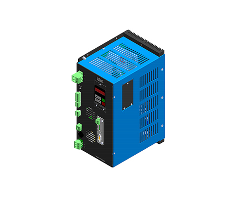
Installation – Mounted on mounting wall DESCRIPTION The DC power supplies from the REOTRON SMP series are primary switched switching power supplies with galvanic isolation from the input to the output. The devices can be used as voltage, current or power regulators. Operation The unit can be operated from an internal display, external control signals of 0…+10V, 0(4)…20mA or optionally by a fieldbus interface such as DeviceNet, ProfiBus, CanBus, EtherCAT, EtherNet/IP and ProfiNet protocols. Input devices The device input is designed for connection to a three-phase mains 3 x 400 V, 50/60 Hz. The compliance of EMC standards is guaranteed by an input-sided PFC-mains filter. Design The devices have a compact design in a 19 inch rackmount chassis and can be delivered as a installation ready control cabinet version or as a tabletop unit (lab version). The devices are air- or water-cooled. Connection The SMP‘s are connected via screw terminals and with cooper terminal buses at high output currents. Like all REO-products, the REOTRON SMP‘s are also available as customized versions. ADVANTAGES Very good cos Φ of 0,95 Compact dimensions Series or parallel connection Air or water- cooling Many options of combinations for different requirements with otherREO product ranges TECHNICAL SPECIFICATION Type REOTRON SMP-KMB Contact Module Input voltage 230 V, +/- 10%, 50/60 Hz, Ripple P-P 100 mV/ 200 mV Setpoint Input 0…+10 V, DC, 0(4)…20mA, Potentiometer 10 kOhm internally via the control display Actual Value Output 0…+10 V, DC, 0(4)…20mA, internally via the control display Interfaces (Option) ProfiBus-DP, DeviceNet, CAN-Bus, ProfiNet, EtherNet/IP, EtherCAT Control Accuracy 1% of the nominal value (higher on reguest) Release 24 V, DC or contact Protection Class Control cabinet installation IP 20 2 x Status Relays Changeover 250 V, 1A Efficiency > 85% Cos Φ 0,95 Operating Temperature 0… 40° C Standards EN 50178, EN 61000-6-2, EN 61000-6-4 REO Series SMP-KMB 10-10 SMP-KMB 10-20 SMP-KMB 10-30 SMP-KMB 10-40 Output power [W] 0…100 0…200 0…300 0…400 Output voltage [V] 0…10 0…10 0…10 0…10 Output current [A] 0…10 0…20 0…30 0…40 Dimensions (WxDxH) [BxTxHE] 154x330x217,5 154x330x217,5 154x330x217,5 154x330x217,5 REO Series SMP-KMB 20-10 SMP-KMB 20-20 SMP-KMB 20-30 SMP-KMB 20-40 Output Power [W] 0…200 0…400 0…600 0…800 Output voltage [V] 0…20 0…20 0…20 0…20 Output current [A] 0…10 0…20 0…30 0…40 Dimensions (WxDxH) [BxTxHE] 154x330x217,5 154x330x217,5 154x330x217,5 154x330x217,5 REO series SMP-KMB 30-10 SMP-KMB 30-20 SMP-KMB 30-30 SMP-KMB 30-40 SMP-KMB 40-10 SMP-KMB 40-20 Output power [W] 0…300 0…600 0…900 0…1200 0…400 0…800 Output voltage [V] 0…30 0…30 0…30 0…30 0…40 0…40 Output current [A] 0…10 0…20 0…30 0…40 0…10 0…20 Dimensions (WxDxH) [BxTxHE] 154x330x217,5 154x330x217,5 154x330x217,5 154x330x217,5 154x330x217,5 154x330x217,5 REO Series SMP-KMB 50-10 SMP-KMB 50-20 SMP-KMB 60-10 Output power [W] 0…500 0…1000 0…600 Output voltage [V] 0…50 0…50 0…60 Output current [A] 0…10 0…20 0…10 Dimensions [BxTxHE] 154x330x217.5 154x330x217.5 154x330x217.5 * Higher services on request