
DC-Link reactor N CNW 891
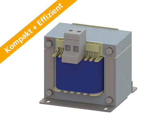
Single-phase DC-link reactor (1 line) Description Compact & efficient Reduce grid disturbances – save energy costs. The DC-link reactor is used for smoothing the DC link current and to reduce mains harmonics in voltage source inverters. The typical combinations of rectifiers and capacitors strains the supply network significantly. For functional reasons, the current consumption of the power supply or the inverter is not sinusoidal but pulsed at the moment of maximum voltage. DC-link reactor reduce the harmonics and relieve the supply network similar to the mains choke. In addition, the DC-link reactor attenuates charging current peak surges of the DC-link capacitors. By using a DC-link reactor the supply network is less burdened with harmonic reactive power. Improvement of the efficiency of a converter (Power Factor Correction). Starting currents and current peak are attenuated up to 70%. Line reactors help to comply with international power quality standards IEEE 519 or EN 61000-3-2. TYPICAL APPLICATIONS Drive systems for motor drives,Mechanical engineering,Elevators/ escalators,Pipes,Conveyor technology,Ventilation and air conditioning,Robotics,Automation technology,Power supplies,Wind turbines Advantages Reduction of harmonics waves Attenuation of current spikes of up to 70% Compact design Advantages over line reactor: Smaller size Lower cost of materials / Price Smaller power loss Production possible according to UL insulation system E251513 Technical Data Nominal voltage: U ≤ 600 V According to: EN 60289 / EN 61558 Test voltage: L-PE 4000 V, AC/50Hz, 60s Insulation class: T40/F Protection rating: IP00 Climatic category: DIN IEC 60068-1 Overload: 1,5 x INenn 1 min / h Design: standing on foot angle Technical specification Type Nominal voltage U [V] Nominal current [A] Inductance [mH] Power dissipation [W] Mass [kg] Mass Cu [kg] N CNW 891 / 8 600 50 / 60 Hz 8 9,4 14 1,4 0,3 N CNW 891 /11 600 50 / 60 Hz 11 6,2 15 2 0,3 N CNW 891 / 15 600 50 / 60 Hz 15 4,8 20 2,8 0,6 N CNW 891 / 20 800 50 / 60 Hz 20 3,3 19 3,6 0,6 N CNW 891 /28 800 50 / 60 Hz 28 2,4 22 3,6 0,8 N CNW 891 / 34 800 50 / 60 Hz 34 2,0 29 4,5 0,8 N CNW 891 / 40 800 50 / 60 Hz 40 1,6 31 7 1 N CNW 891 / 55 800 50 / 60 Hz 55 1,2 43 8 1,2 N CNW 891 / 70 800 50 / 60 Hz 70 0,98 49 10,5 1,4 N CNW 891 / 85 800 50 / 60 Hz 85 0,81 60 13,6 1,8 N CNW 891 / 100 800 50 / 60 Hz 100 0,67 70 14 2,5 DIMENSIONS IN MM Type Lenght L1 (mm) Broad B1 (mm) Broad B2 (mm) High max. H (mm) Mounting N1 (mm) Attachment N2 (mm) Attachment D1 (mm x mm) Connection terminal/ Cable lug [mm²] Connection PE Connection A1 (mm) Design N CNW 891 / 8 84 76 62 80 64 48 5 x 8 2,5 Flat plug 6,3 x 0,8 1 N CNW 891 /11 84 90 76 80 64 62 5 x 8 2,5 Flat plug 6,3 x 0,8 1 N CNW 891 / 15 96 95 88 85 84 72 6 x 11 2,5 Flat plug 6,3 x 0,8 1 N CNW 891 / 20 96 138 102 85 84 85 6 x 11 10 (m5) M5 40 2 N CNW 891 /28 96 138 102 85 84 85 6 x 11 16 (M5) M5 40 2 N CNW 891 / 34 105 138 105 95 84 87 6 x 11 16 (M5) M5 40 2 N CNW 891 / 40 120 155 120 105 90 105 6 x 11 16 (M5) M6 45 2 N CNW 891 / 55 150 138,5 107,5 135 122 87,5 7 x 13 16 (M5) M6 45 2 N CNW 891 / 70 150 159 124,5 135 122 104,5 7 x 13 25 (M8) M6 45 2 N CNW 891 / 85 150 185,5 150,5 135 122 130,5 7 x 13 25 (M8) M6 45 2 N CNW 891 / 100 174 162,5 121 150 135 101 7 x 13 35 (M8) M8 50 2 Data sheet Download our extensive catalog and discover many other REO products. Download Data sheet Certifications
Motor Choke CNW M 854
Reduce voltage rise (< 200V / µs) and distortions – optimally protect electrical consumers.
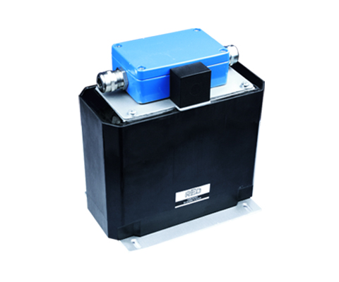
du/dt Drossel CNW M 833

Fully Potted Three-Phase Du/dt Filter (Protection Class: IP00 – IP66) Description Reduce voltage rise to < 500V / µs – protect electrical loads and insulation cost-effectively. A simple and cost-effective method to reduce the voltage rise rate is to use a du/dt filter. The filter dampens the voltage rise to acceptable values and prevents overvoltages on long supply lines. Losses and heating are minimised and the leakage current is reduced. By limiting the voltage gradient, the motor insulation is protected and the service life is extended. The EMC interference in the radiation range from 1 MHz to 30 MHz is also reduced. Voltage rises are reduced to < 500V / µs. Advantages optimal mechanical protection of the Drossel Protection Class: IP00 – IP66 Protection for electrical consumers Limitation of voltage rise to < 500V/µs extended service life for electrical consumers low leakage currents on the motor Reduced losses Very low noise Easy construction Production according to UL insulation system E251513 possible Typical Applications Drive systems for motor drives: Mechanical engineering, Elevators / escalators, Pipes, Conveyor technology, Ventilation and air conditioning, Robotics, Automation technology, Power supplies and Wind turbines Technical data Type Degree of protection Rated voltage [V] Rated current [A] Inductance [mH] Capacitance [pF] Weight [kg] Terminal [mm²] Cable gland CNW M 833 / 8 IP 66 3 x 400 ≥ 60 Hz 8 2 330 3,3 2,5 M20x1.5 CNW M 833 / 16 IP 66 16 0,9 330 4,5 6 M25x1.5 CNW M 833 / 36 IP 65 36 0,42 1500 9 16 M32x1.5 CNW M 833 / 60 IP 65 60 0,27 2200 25 35 M40x1.5 CNW M 833 / 90 IP 65 90 0,17 4700 27 35 M40x1.5 CNW M 833 / 180 IP 65 175 0,09 10000 40 95 M63x1.5 Dimensions in mm Type Dimensions L1 [mm] L2 [mm] L3 [mm] B1 [mm] B2 [mm] B3 [mm] B4 [mm] B5 [mm] H1 [mm] H2 [mm] H3 [mm] N1 [mm] N2 [mm] D [mm] CNW M 833 / 8 170 140 150 80 80 55 20,5 5,5 170 57 75 135 65 5.5×7 CNW M 833 / 16 180 140 170 85 80 65 10,5 5,5 170 57 75 155 70 5.5×7 CNW M 833 / 36 245 175 175 115 120 80 20 20 250 140 110 155 95 5.5×15 CNW M 833 / 60 315 249 255 180 175 120 30 27 323 218 105 185 150 9×13 CNW M 833 / 90 315 250 255 180 175 120 30 25 325 218 105 185 150 9×13 CNW M 833 / 180 355 270 – 127 200 160 105 8 350 220 130 185 105 10×18 Datasheet All data and configurations can be found in our product datasheet. Download Datasheet Certifications
Test reactor NPT 8929
Single-phase test reactor Description These chokes are used in test laboratories as load chokes. They can be interconnected (almost) arbitrarily. If these chokes are used with appropriate resistors, testing under various cos(phi) is possible. This is required, for example, to test the connection and switching behavior of components Advantages Robust design High flexibility compact design Low losses Technical data Insulation class: F at 40° C Climatic category: 25/085/21 DIN IEC 68 Part 1 Max. winding temperature: 125° C Protection class: IP00 Nominal Voltage: 230 V Rated current: 0,5 – 32,5 A Inductance: 0,127 – 3180 mH Type Rated voltage [V] Rated current [A] Inductance [mH] DC-Resistance [mΩ] Power loss [W] NPT 8929 / 0,5 230 0,5 3180 55670,2 23 NPT 8929 / 1,25 230 1,25 1270 16880,0 43 NPT 8929 / 1,66 230 1,66 955 9977, 8 47 NPT 8929 / 2,5 230 2,5 636 6388,5 66 NPT 8929 / 5 230 5,0 318 1782,5 94 NPT 8929 / 32,5 230 32,5 0,318 0,0 39 NPT 8929 / 32,5 230 32,5 0,127 7,0 13 NPT 8929 / 32,5 230 32,5 0,318 0,0 27 Dimensions in MM Type L [mm] B [mm] H [mm] N1 [mm] N2 [mm] øD1 [mm] Connection [mm²] Copper [kg] Weight [kg] NPT 8929 / 0,5 120 96 205 76 77 7 x 13 2,5 0,7 5 NPT 8929 / 1,25 160 105 265 100 81 7 x 13 2,5 2 9,8 NPT 8929 / 1,66 160 115 270 100 91 7 x 13 2,5 3,1 12,2 NPT 8929 / 2,5 200 122 310 124 94 10 x 18 4 3,9 17 NPT 8929 / 5 240 153 355 144 125 10 x 18 4 7,3 29 NPT 8929 / 32,5 120 96 208 76 77 7 x 13 16 0,84 6,5 NPT 8929 / 32,5 100 82 190 63 65 6 x 10 16 0,44 3,6 NPT 8929 / 32,5 120 96 208 76 77 7 x 13 16 0,94 6,5
Test Reactor NPT 8919

Single-phase iron core reactor Description These chokes are used as load chokes in testing laboratories. They can be interconnected (almost) arbitrarily. If these chokes are used with appropriate resistors, testing is possible under various cos(phi). This is required, for example, to test the connection and switch-on behavior of components. Advantages Robust design High flexibility compact design Low losses Technical data Insulation class: F at 40° C Climatic category: 25/085/21 DIN IEC 68 Part 1 Max. winding temperature: 125° C Protection class: IP00 Nominal voltage: 230 – 600 V Nominal current: 1.5 – 32.5 A Inductance: 0.031 – 71 mH Optional extras Also available as IP 54 with: Input cable/output cable Input cable/output socket Complete cable connection solution for mains, output and control connections
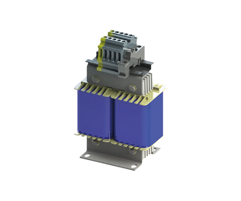
Harmonic Filter CNW 999

Compensation choke (7 or 14% detuning factor) Description Detuning (p) of reactive current and harmonic compensation systems; protection of the capacitors Advantages small inductance tolerance Low-noise linear behavior even with currents greater than the rated current optional connection via terminals or cable Technical data According to: DIN EN 61558-2-20 Test voltage: L-L 2100 V, DC 1 min L-PE 2700 V, DC 1 min Overload: 1,5 x INenn 1 min / h Climate category: DIN IEC 60068-1 Thermal class: H Protection class: IP00 Output voltage: 25 – 600 V Output current: 2 – 600 A Output power: 1000 – 15000 W Input voltage switchable: Input voltage switchable [V] V Type detuning factor 7% Reactive power capacitors [kVAr] Resonance frequency [Hz] Detuning factor (p) [%] Rated current [A] Current @ 50Hz [A] Inductance per strand [mH] Copper [kg] Weight [kg] CNW 999/10/6 6,25 189 7 10,6 10,0 6,0 3 8 CNW 999/19/3 12,5 189 7 20,5 19,0 3,0 4 9 CNW 999/38/1,53 25 189 7 41,0 38,0 1,53 1 17 CNW 999/75/0,78 50 189 7 80,0 75,0 0,78 1 28 Type detuning factor 14% Reactive power capacitors [kVAr] Resonance frequency [Hz] Detuning factor (p) [%] Rated current [A] Current @ 50Hz [A] Inductance per strand [mH] Copper [kg] Weight [kg] CNW 999/9/14,5 6,25 134 14 9,1 9,0 14,5 5 9 CNW 999/19/6,9 12,5 134 14 19,1 19,0 6,9 5 15 CNW 999/38/3,5 25 134 14 38,2 38,0 3,5 1 24 CNW 999/76/1,73 50 134 14 76,5 76,0 1,73 1 43 Dimensions in mm Type detuning factor 7% L [mm] B [mm] H [mm] N1 [mm] N2 [mm] D1 [mm] D2 [mm] Distance [mm] Weight [kg] CNW 999/10/6 190 101 155 170 69 8×12 – 30 7 CNW 999/19/3 190 111 155 170 79 8×12 – 30 8 CNW 999/38/1,53 240 150 205 185 97 10×18 9 55 17 CNW 999/75/0,78 265 172 225 200 122 10×18 9 55 28 Type detuning factor 14% L [mm] B [mm] H [mm] N1 [mm] N2 [mm] D1 [mm] D2 [mm] Distance [mm] Weight [kg] CNW 999/9/14,5 190 97 157 170 69 8×12 – 30 9 CNW 999/19/6,9 240 111 209 185 88 8×12 – 45 15 CNW 999/38/3,5 265 265 225 200 104 10×18 9 55 24 CNW 999/76/1,73 300 197 225 224 144 10×18 9 65 43
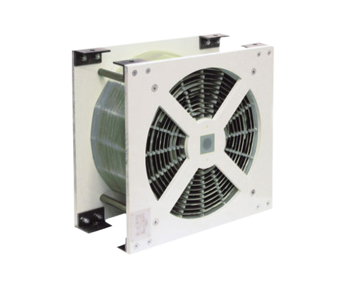
Air Choke Ld 220
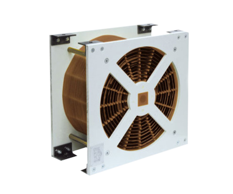
Air choke with aluminium copper/disc winding DESCRIPTION Air reactors are particularly used where high inductive linearity is required. Due to their relatively simple mechanical structure, they are not only compact, but also very robust. With our expertise, the REO air reactors perform to the required standard, even in the most arduous conditions. REO Mix & Match principle With REO Mix & Match you can choose from a wide range of of options – combine the various options in order to always get the best product for your application. REO is able to offer different designs and winding techniques, a variety of conductor materials and structures. Depending on the specific requirements, we are able to produce an optimal solution by combining these parameters to provide the perfect solution. Optional Layer winding/Disc winding Aluminium, Copper or aluminium + copper Protections: Paint coating, protective coating, housing or REO Xtreme Cooling fan/unit Sensors: Switch NO / NC, PT100, NTC, PTC ADVANTAGES No saturation Wide range of material selection Special protective coating High linearity L (i) Very good mechanical strength No hysteresis Optimal weight by forced air cooling Directional air flow through GRP conduits Very efficient liquid cooling option (waveguide) Can be used almost anywhere PTC Technical Data Frequency of the current: DC and AC Tolerances: + 10 / – 10 %, + 5 / – 5 % Taps: By default, no taps (available on request) Insulation: F or H Cooling method and cooling liquid according to IEC 60310: AN, AF or WF Test voltage: up to 12kV 60s 50Hz, up to 25kV 1,2/50µs Mounting: Suspended, vertical or horizontal Mechanical strength, mechanical simulation (FEM): EN 12663 Shock – and vibration stress: IEC 61373 Kat. 1 Kl. B Rated current: 200 – 700 A Inductance: 0,5 – 4 mH Type Inductance (mH) Cooling 3 m/s Cooling 5 m/s Cooling 8 m/s I [A] magn. Energy [J] P [kVA] at 20°C I [A] magn. Energy [J] P [kVA] at 20°C I [A] magn. Energy [J] P [kVA] at 20°C LD 220/200/0,5 0,5 200 10 0,7 250 15,6 1,1 300 22,5 1,6 LD 220/400/0,5 0,5 400 40 1,8 500 62,5 2,9 600 90 4,2 LD 220/700/0,5 0,5 700 122,5 2,4 500 62,5 2,9 600 90 4,2 LD 220/200/1 1 200 20 1,1 250 31,3 1,7 300 45 2,4 LD 220/400/1 1 400 80 2,8 500 125 4,4 600 180 6,3 LD 220/700/1 1 700 245 3,8 850 361,3 5,5 100 5 7,7 LD 220/200/2 2 200 40 1,7 250 62,5 2,6 300 90 3,7 LD 220/400/2 2 400 160 4,4 500 250 6,9 600 360 10 LD 220/700/2 2 700 490 5,7 850 722,5 8,4 1000 1000 11,6 LD 220/200/4 4 200 80 2,5 250 125 3,9 300 180 5,6 LD 220/400/4 4 400 320 6,9 500 500 10,8 600 720 15,6 LD 220/700/4 4 700 980 8,7 850 1445 12,8 1000 2000 17,7 Dimensions in mm Type B [mm] H [mm] T [mm] Copper [kg] Weight [g] LD 220/200/0,5 250 250 180 11,4 16 LD 220/400/0,5 350 350 180 20,9 29 LD 220/700/0,5 400 400 370 74,8 86 LD 220/200/1 300 300 220 17,6 33 LD 220/400/1 400 400 220 32,5 37 LD 220/700/1 400 400 450 116 124 LD 220/200/2 350 350 230 26,7 40 LD 220/400/2 400 400 310 51,4 87 LD 220/700/2 450 450 490 175 182 LD 220/200/4 400 400 250 40,2 54 LD 220/400/4 420 420 400 80,3 97 LD 220/700/4 500 500 570 267 301
Air reactor LD 120

Air reactor with copper/disc winding DESCRIPTION Air reactors are used when a particularly high linearity is required. By its relatively simple structure, they are not only compact, but also very stable. With our expertise, REO air chokes maintain their full functionality even under extreme conditions. With our expertise, the REO air reactors perform to the required standard, even in the most arduous conditions. REO Mix & Match principle With REO Mix & Match you can choose from a wide range of of options – combine the various options in order to always get the best product for your application. REO is able to offer different designs and winding techniques, a variety of conductor materials and structures. Depending on the specific requirements, we are able to produce an optimal solution by combining these parameters to provide the perfect solution. Optional Layer winding/Disc winding Aluminium, Copper or aluminium + copper Protections: Paint coating, protective coating, housing or REO Xtreme Cooling fan/unit Sensors: Switch NO / NC, PT100, NTC, PTC ADVANTAGES No saturation Wide range of material selection Special protective coating High linearity L (i) Very good mechanical strength No hysteresis Optimal weight by forced air cooling Directional air flow through GRP conduits Very efficient liquid cooling option (waveguide) Able to be universally applied. TECHNICAL SPECIFICATION Frequency of the current: DC and AC Tolerances: + 10 / – 10 %, + 5 / – 5 % Taps: By default, no taps (available on request) Insulation: F or H Cooling method and cooling liquid according to IEC 60310: AN, AF or WF Test voltage: up to 12kV 60s 50Hz, up to 25kV 1,2/50µs Mounting: Suspended, vertical or horizontal Mechanical strength, mechanical simulation (FEM): EN 12663 Shock – and vibration stress: IEC 61373 Kat. 1 Kl. B Rated Current: 200 – 1000A Type Inductance (mH) Cooling 3 m/s Cooling 5 m/s Cooling 8 m/s I [A] magn. Energy [J] P [kVA] at 20°C I [A] magn. Energy [J] P [kVA] at 20°C I [A] magn. Energy [J] P [kVA] at 20°C LD 120/200/0,2 0,2 200 4 0,4 240 5,8 0,6 285 8,1 0,8 LD 120/400/0,2 0,2 400 16 0,9 510 26 1,5 610 37,2 2,1 LD 120/700/0,2 0,2 700 49 1,3 860 74 2 1030 106,1 2,9 LD 120/1000/0,2 0,2 1000 100 2,2 1170 136,9 3 1400 196 4,2 LD 120/200/0,5 0,5 200 10 0,7 245 15 1 295 21,8 1,5 LD 120/400/0,5 0,5 400 40 1,6 510 65 2,5 600 90 3,5 LD 120/700/0,5 0,5 700 122,5 2,4 870 189,2 3,7 1030 265,2 5,2 LD 120/1000/0,5 0,5 1000 250 3,6 1200 360 5,1 1440 518,4 7,4 LD 120/200/1 1 200 20 1 255 32,5 1,6 300 45 2,2 LD 120/400/1 1 400 80 2,4 500 125 3,7 600 180 5,4 LD 120/700/1 1 700 245 3,7 870 378,5 5,8 1030 530,5 8,1 LD 120/1000/1 1 1000 500 5,5 1200 720 7,9 1420 1008,2 11,1 LD 120/200/2 2 200 40 1,6 250 62,5 2,4 300 90 3,5 LD 120/400/2 2 400 160 3,8 500 250 5,9 600 360 8,5 LD 120/700/2 2 700 490 5,8 870 756,9 8,9 1040 1081,6 12,7 LD 120/1000/2 2 1000 1000 8,5 1190 1416,1 12,1 1410 1988,1 17 LD 120/200/4 4 200 80 2,3 255 130,1 3,8 300 180 5,3 LD 120/400/4 4 400 320 6,3 500 500 9,8 600 720 14,1 LD 120/700/4 4 700 980 8,6 810 1312,2 13,4 1040 2163,2 19,1 LD 120/1000/4 4 1000 2000 12,7 1250 3125 19,9 1500 4500 28,7 LD 120/200/8 8 200 160 3,6 250 250 5,6 300 360 8,1 LD 120/400/8 8 400 640 9,3 500 1000 14,5 600 1440 20,8 LD 120/700/8 8 700 1960 13,5 870 3027,6 20,9 1050 4410 30,4 Dimensions in mm Type B [mm] H [mm] T [mm] Copper [kg] Weight [g] LD 120/200/0,2 250 250 150 6,6 11 LD 120/400/0,2 350 350 180 16 25 LD 120/700/0,2 350 350 280 44,6 54 LD 120/1000/0,2 400 400 420 77,2 92 LD 120/200/0,5 300 300 180 11,9 18 LD 120/400/0,5 400 400 210 27,8 38 LD 120/700/0,5 400 400 350 80 93 LD 120/1000/0,5 500 500 360 127 147 LD 120/200/1 350 350 170 17,8 26 LD 120/400/1 450 450 240 39,1 57 LD 120/700/1 450 450 460 125 139 LD 120/1000/1 550 550 490 197 222 LD 120/200/2 400 400 190 26,9 37 LD 120/400/2 450 450 360 67,5 83 LD 120/700/2 450 450 580 192 217 LD 120/1000/2 550 550 640 305 341 LD 120/200/4 400 400 230 40,6 55 LD 120/400/4 450 450 530 109 129 LD 120/700/4 550 550 620 289 326 LD 120/1000/4 600 600 820 503 555 LD 120/200/8 450 450 320 64,1 81 LD 120/400/8 500 500 600 169 192 LD 120/700/8 550 550 830 453 506
Air Choke LD 110
Air choke with aluminium/layer winding DESCRIPTION Air reactors are particularly used where high inductive linearity is required. Due to their relatively simple mechanical structure, they are not only compact, but also very robust. With our expertise, the REO air reactors perform to the required standard, even in the most arduous conditions. REO Mix & Match principle With REO Mix & Match you can choose from a wide range of of options – combine the various options in order to always get the best product for your application. REO is able to offer different designs and winding techniques, a variety of conductor materials and structures. Depending on the specific requirements, we are able to produce an optimal solution by combining these parameters to provide the perfect solution. Optional Layer winding/Disc winding Aluminium, Copper or aluminium + copper Protections: Paint coating, protective coating, housing or REO Xtreme Cooling fan/unit Sensors: Switch NO / NC, PT100, NTC, PTC ADVANTAGES No saturation effects Diverse choice of materials Special protective coating High linearity L (i) Very good mechanical resilience No hysteresis losses Optimal weight through forced air cooling Directed air flow through GRP pipes Very efficient liquid cooling possible (waveguide) Can be used almost anywhere PTC Technical Data Frequency of the current: DC and AC Tolerances: + 10 / – 10 %, + 5 / – 5 % Taps: By default, no taps (available on request) Insulation: F or H Cooling method and cooling liquid according to IEC 60310: AN, AF or WF Test voltage: up to 12kV 60s 50Hz, up to 25kV 1,2/50µs Mounting: Suspended, vertical or horizontal Mechanical strength, mechanical simulation (FEM): EN 12663 Shock – and vibration stress: IEC 61373 Kat. 1 Kl. B Rated current: 50 – 1000 A Inductance: 0,2 – 8 mH Technical Data Type Inductance [mH] Cooling 3 m/s Cooling 5 m/s Cooling 8 m/s I [A] magn. Energy [J] P [kVA] at 20°C I [A] magn. Energy [J] P [kVA] at 20°C I [A] magn. Energy [J] P [kVA] at 20°C LD 110/70/0,2 0,2 70 0,49 0,2 87 0,8 0,3 105 1,1 0,4 LD 110/100/0,2 0,2 100 1 0,2 133 1,8 0,3 160 2,6 0,5 LD 110/200/0,2 0,2 200 4 0,4 240 5,8 0,6 290 8,4 0,8 LD 110/400/0,2 0,2 400 16 0,9 480 23 1,3 570 32,5 1,9 LD 110/700/0,2 0,2 700 49 1,5 820 67,2 2 980 96 2,9 LD 110/1000/0,2 0,2 1000 100 2,3 1210 146,4 3,4 1470 216,3 4,7 LD 110/50/0,5 0,5 50 0,625 0,2 60 0,9 0,3 70 1,3 0,4 LD 110/100/0,5 0,5 100 2,5 0,4 118 3,5 0,6 140 4,9 0,8 LD 110/200/0,5 0,5 200 10 0,7 235 13,8 1 280 19,6 1,4 LD 110/400/0,5 0,5 400 40 1,6 485 58,8 2,3 585 84,1 3,3 LD 110/700/0,5 0,5 700 122,5 2,5 820 168,1 3,6 970 235,2 5 LD 110/1000/0,5 0,5 1000 250 3,9 1230 378,2 5,9 1460 532,9 8,2 LD 110/50/1 1 50 1,25 0,3 60 1,8 0,5 72´3 2,7 0,7 LD 110/100/1 1 100 5 0,6 125 7,8 1 148 11 1,4 LD 110/200/1 1 200 20 1 240 28,8 1,5 290 42,1 2,2 LD 110/400/1 1 400 80 2,5 490 120,1 3,7 580 168,2 5,2 LD 110/700/1 1 700 245 3,8 830 344,5 5,3 980 480,2 7,4 LD 110/1000/1 1 1000 500 6 1240 768,8 9,3 1480 1095,2 13,2 LD 110/50/2 2 50 2,5 0,5 62 3,8 0,8 84 7,1 1,1 LD 110/100/2 2 100 10 1 122 14,9 1,5 145 21 2,1 LD 110/200/2 2 200 40 1,6 245 60 2,4 290 84,1 3,4 LD 110/400/2 2 400 160 3,9 485 235,2 5,7 575 330,6 8 LD 110/700/2 2 700 490 6 825 680,6 8,3 980 960,4 11,8 LD 110/1000/2 2 1000 1000 9,1 1230 1512,9 13,8 1450 2102,5 19,7 LD 110/50/4 4 50 5 0,8 62 7,7 1,2 73 10,7 1,6 LD 110/100/4 4 100 20 1,5 125 31,3 2,3 150 45 3,3 LD 110/200/4 4 200 80 2,4 245 120,1 3,6 290 168,2 5,1 LD 110/400/4 4 400 320 6,2 490 480,2 9,3 585 684,5 13,2 LD 110/700/4 4 700 980 9,2 830 1377,8 12,9 980 1920,8 18 LD 110/1000/4 4 1000 2000 13,8 1240 3075,2 21,2 1480 4380,8 30,2 LD 110/50/8 8 50 10 1,1 62 15,4 1,7 74 21,9 2,5 LD 110/100/8 8 100 40 2,2 130 67,6 3,7 155 96,1 5,2 LD 110/200/8 8 200 160 3,8 245 240,1 5,7 290 336,4 8 LD 110/400/8 8 400 640 9,4 490 960,4 14,1 580 1345,6 19,7 LD 110/700/8 8 700 1960 13,8 820 2689,6 19 980 3841,6 27,1 Dimensions in mm Type B [mm] H [mm] T [mm] Copper [kg] Weight [g] LD 110/70/0,2 150 150 100 1 4 LD 110/100/0,2 200 200 120 2 5 LD 110/200/0,2 300 300 110 4,5 11 LD 110/400/0,2 350 350 190 10,9 21 LD 110/700/0,2 400 400 250 29 42 LD 110/1000/0,2 400 400 450 51,1 68 LD 110/50/0,5 200 200 80 1 4 LD 110/100/0,5 200 200 140 2,5 6 LD 110/200/0,5 300 300 200 8,3 15 LD 110/400/0,5 400 400 210 18,6 30 LD 110/700/0,5 400 400 380 52 69 LD 110/1000/0,5 500 500 420 84,7 106 LD 110/50/1 250 250 80 1,3 5 LD 110/100/1 250 250 130 3,7 8 LD 110/200/1 350 350 180 12,1 21 LD 110/400/1 450 450 250 29 43 LD 110/700/1 550 550 340 75,4 97 LD 110/1000/1 550 550 550 132 158 LD 110/50/2 250 250 100 2,1 6 LD 110/100/2 250 250 220 6 11 LD 110/200/2 400 400 230 18,8 29 LD 110/400/2 450 450 350 45,2 62 LD 110/700/2 500 500 500 119 142 LD 110/1000/2 550 550 660 200 232 LD 110/50/4 250 250 140 3,2 7 LD 110/100/4 300 300 200 9,8 15 LD 110/200/4 400 400 250 28,4 41 LD 110/400/4 450 450 520 72,3 95 LD 110/700/4 550 550 620 182 212 LD 110/1000/4 630 630 750 302 348 LD 110/50/8 250 250 160 4,7 10 LD 110/100/8 350 350 190 12,9 21 LD 110/200/8 450 450 350 44 6
Air reactor LD 100
Air reactor with copper/layer winding DESCRIPTION Air reactors are particularly used where high inductive linearity is required. Due to their relatively simple mechanical structure, they are not only compact, but also very robust. With our expertise, the REO air reactors perform to the required standard, even in the most arduous conditions. REO Mix & Match principle With REO Mix & Match you can choose from a wide range of of options – combine the various options in order to always get the best product for your application. REO is able to offer different designs and winding techniques, a variety of conductor materials and structures. Depending on the specific requirements, we are able to produce an optimal solution by combining these parameters to provide the perfect solution. Optional Layer winding/Disc winding Aluminium, Copper or aluminium + copper Protections: Paint coating, protective coating, housing or REO Xtreme Cooling fan/unit Sensors: Switch NO / NC, PT100, NTC, PTC ADVANTAGES No saturation effects Diverse choice of materials Special protective coating High linearity L (i) Very good mechanical resilience No hysteresis losses Optimal weight through forced air cooling Directed air flow through GRP pipes Very efficient liquid cooling possible (waveguide) Can be used almost anywhere PTC Technical Data Frequency of the current: DC and AC Tolerances: + 10 / – 10 %, + 5 / – 5 % Taps: By default, no taps (available on request) Insulation: F or H Cooling method and cooling liquid according to IEC 60310: AN, AF or WF Test voltage: up to 12kV 60s 50Hz, up to 25kV 1,2/50µs Mounting: Suspended, vertical or horizontal Mechanical strength, mechanical simulation (FEM): EN 12663 Shock – and vibration stress: IEC 61373 Kat. 1 Kl. B Rated current: 50 – 1000 A Inductance: 0,2 – 8 mH Technical Data Type Inductance (mH) Cooling 3 m/s Cooling 5 m/s Cooling 8 m/s I [A] magn. Energy [J] P [kVA] at 20°C I [A] magn. Energy [J] P [kVA] at 20°C I [A] magn. Energy [J] P [kVA] at 20°C LD 100/50/0,2 0,2 50 0,25 0,1 60 0,4 0,1 70 0,5 0,2 LD 100/100/0,2 0,2 100 1 0,2 120 1,4 0,2 145 2,1 0,4 LD 100/200/0,2 0,2 200 4 0,4 240 5,8 0,6 280 7,8 0,8 LD 100/400/0,2 0,2 400 16 0,9 490 24 1,4 585 34,2 1,9 LD 100/700/0,2 0,2 700 49 1,6 850 72,3 2,3 1020 104 3,3 LD 100/1000/0,2 0,2 1000 100 1,7 1225 150,1 2,6 1450 210,3 3,7 LD 100/50/0,5 0,5 50 0,625 0,2 60 0,9 0,2 72 1,3 0,3 LD 100/100/0,5 0,5 100 2,5 0,3 122 3,7 0,4 145 5,3 0,6 LD 100/200/0,5 0,5 200 10 0,6 245 15 0,9 295 21,8 1,3 LD 100/400/0,5 0,5 400 40 1,5 490 60 2,2 585 85,6 3,1 LD 100/700/0,5 0,5 700 122,5 2,7 865 187,1 4,1 1030 265,2 5,7 LD 100/1000/0,5 0,5 1000 250 3,1 1200 360 4,5 1430 511,2 6,4 LD 100/50/1 1 50 1,25 0,2 60 1,8 0,3 72 2,6 0,5 LD 100/100/1 1 100 5 0,5 125 7,8 0,8 147 10,8 1,1 LD 100/200/1 1 200 20 0,9 240 28,8 1,4 290 42,1 2 LD 100/400/1 1 400 80 2,2 490 120,1 3,3 585 171,1 4,7 LD 100/700/1 1 700 245 4,1 870 378,5 6,4 1030 530,5 8,9 LD 100/1000/1 1 1000 500 5 1200 720 7,1 1430 1022,5 10,1 LD 100/50/2 2 50 2,5 0,4 63 4 0,6 75 5,6 0,8 LD 100/100/2 2 100 10 0,9 125 15,6 0,8 147 21,6 1,1 LD 100/200/2 2 200 40 1,4 245 60 2,2 290 84,1 3 LD 100/400/2 2 400 160 3,6 490 240,1 5,3 580 336,4 7,5 LD 100/700/2 2 700 490 6,5 870 756,9 10 1030 1060,9 14,1 LD 100/1000/2 2 1000 1000 7,2 1250 1562,5 11,2 1480 2190,4 15,8 LD 100/50/4 4 50 5 0,6 63 7,9 0,9 75 11,3 1,3 LD 100/100/4 4 100 20 1,3 123 30,3 1,9 145 42,1 2,7 LD 100/200/4 4 200 80 2,2 245 120,1 3,3 290 168,2 4,6 LD 100/400/4 4 400 320 5,6 490 480,2 8,5 580 672,8 11,9 LD 100/700/4 4 700 980 9,9 870 1513,8 15,2 1040 2163,2 21,8 LD 100/1000/4 4 1000 2000 11 1250 3125 17,8 1480 4380,8 24,9 LD 100/50/8 8 50 10 11,4 64 16,4 1,4 77 23,7 2 LD 100/100/8 8 100 40 1,9 125 62,5 3 150 90 4,4 LD 100/200/8 8 200 160 3,4 245 240,1 5 290 336,4 7,1 LD 100/400/8 8 400 640 8,5 490 960,4 12,7 585 1368,9 18,2 LD 100/700/8 8 700 1960 15,3 875 3062,5 23,9 1050 4410 34,4 Dimensions in mm Type B [mm] H [mm] T [mm] Copper [kg] Weight [g] LD 100/50/0,2 150 150 60 1,5 5 LD 100/100/0,2 180 180 80 3,6 7 LD 100/200/0,2 220 220 130 8,5 13 LD 100/400/0,2 350 350 170 19,7 27 LD 100/700/0,2 350 350 270 51,3 62 LD 100/1000/0,2 400 400 340 110 123 LD 100/50/0,5 180 180 60 2,2 6 LD 100/100/0,5 200 200 90 6,2 10 LD 100/200/0,5 300 300 140 16,7 23 LD 100/400/0,5 400 400 170 36,5 45 LD 100/700/0,5 400 400 270 86,4 98 LD 100/1000/0,5 500 500 310 173 188 LD 100/50/1 180 180 70 3,3 7 LD 100/100/1 250 250 110 8,6 12 LD 100/200/1 350 350 140 23,5 31 LD 100/400/1 420 420 190 55 66 LD 100/700/1 420 420 360 134,3 148 LD 100/1000/1 550 550 400 266 283 LD 100/50/2 250 250 80 5,1 9 LD 100/100/2 250 250 120 11,7 16 LD 100/200/2 400 400 150 35,9 45 LD 100/400/2 420 420 280 88,9 102 LD 100/700/2 450 450 480 212 234 LD 100/1000/2 550 550 580 460 495 LD 100/50/4 250 250 100 7,8 12 LD 100/100/4 300 300 130 17,4 23 LD 100/200/4 400 400 200 55,1 68 LD 100/400/4 450 450 410 141 157 LD 100/700/4 550 550 550 321 354 LD 100/1000/4 550 550 770 727 770 LD 100/50/8 250 250 120 11,8 16 LD 100/100/8 350 350 140 26,9 36 LD 100/200/8 450 450 240 83,9 98